Copyright© 1998 Mitchell Repair Information Company, LLC Wednesday, November 12, 2003 09:26PM
1990 ELECTRICAL Alternators - Delco-Reny
A1 1 IVbdel s
Two types of alternators are used. The SI (Systems Integral) series alternator is a Delcotron type and is used in the Grand Wtgoneer and Wangler. This series is serviceable, with an internal voltage regulator that is not adjustable. The CS (Charging System) series alternator is used in the Cherokee, Comanche and Wgoneer. This series is a sealed unit and is not serviceable. It has a solid state internal voltage regulator and is not adjustable.
ALTERNATOR APPLI CATI ON TABLE
IVbdel Alternator Used
Cherokee ......................................... CS
Comanche ......................................... CS
Grand Wtgoneer ................................... SI
Wtgoneer ......................................... CS
W angl er ......................................... SI
The solid state voltage regulator varies voltage to compensate for current load and engine temperature. Voltage is regulated by controlling rotor field current. Regulator switches rotor field current "on" and "off" at a fixed frequency of approximately 400 cycles per second. If s ys t em vol t age is too high or too low, voltage regulator will turn ON charge indicator light whi 1 e engine is running.
A rectifier bridge, connected to stator windings, contains 6 diodes (3 positive and 3 negative) molded into an assembly. This rectifier bridge changes stator AC voltage into DC voltage, whi ch appears at battery output terminal.
Alternator field current is supplied through a diode trio connected to stator windings. A capacitor is mounted to end frame, protecting rectifier bridge and diodes from high voltage and suppressing radio interference noise.
NOTE: See the TROUBLE SHOOTING - BASIC PROCEDURES article
in the GENERAL TROUBLE SHOOTING section.
NOTE: Before testing, check all terminals connections. Check
alternator mounting bolts and drive belt tension. Ensure
battery is fully charged.
1) If an overcharging condition is suspected, run engine at a moderate speed. Connect a voltmeter across battery terminals. If voltmeter indicates more than 16 volts, replace alternator.
2) If an undercharging condition is suspected, disconnect 2-wi r e connector f r om al t er nat or . Turn ignition on with engine off.
Connect a voltmeter between terminal " L" in wiring harness and ground.
Recor d r eadi ng.
3) If terminal "I" is used, connect voltmeter between terminal "I" and ground. Record reading. If voltmeter reads battery voltage, circuits are okay. If voltmeter reads zero, this indicates an open circuit between terminal checked and battery. Repair as necessary.
If an overcharging condition is suspected, run engine at a moderate speed. Connect a voltmeter across battery terminals. If voltmeter indicates more than 16 volts, replace alternator.
1) Run engine at moderate speed, all electrical accessories off. Nfeasure voltage across battery, if above 16 volts, replace alter nat or .
2) Connect an ammeter in circuit at "BAT" terminal of alternator. Turn on all available accessories. Connect a battery load tester across battery. Operate engine at 2000 RPM and adjust battery load tester as required to obtain maxi mum cur r ent output while maintaining 13 volts or more.
3) Output mist be within 15 amps of rated output stamped on alternator. If output is not within 15 amps of rated output, replace alter nat or .
1) If an overcharging condition is suspected, attach a voltmeter across battery terminals. Run engine at a moderate speed with all accessories off. If voltmeter reads 15.5 volts or more, remove alternator for repair.
c
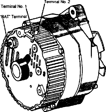
2) on and leave all wiring leads connected. Connect a voltmeter from alternator BAT terminal to ground. Voltmeter should read 12.5 volts. Backprobe with voltmeter between No. 1 terminal and ground. Voltmeter should read 2-4 volts. See Fig. 1.
 |
|
Fig. 1: Locating Alternator Terminal (SI Series) Courtesy of Chrysler Mttors. |
3) Backprobe with voltmeter between No. 2 terminal and ground. Voltmeter should read 12.5 volts. A zero reading on any connection indicates an open between connection and battery. Opens in the No. 2 lead will prevent alternator from turning on.
1) Connect an ammeter or alternator tester in circuit at BAT terminal of alternator. Turn on all available accessories. Connect a battery load tester across battery. Operate engine at 2000 RPM and adjust battery load tester as required to obtain naximim current
out put.
2) Output mist be within 10 amps of rated output stamped on alternator. If not, ground field winding by inserting a screwdriver into test hole, touching tang to alternator case. See Fig. 2. Repeat step 1).
Fig. 2: Locating Alternator Test Ffol e (SI Series)
Courtesy of Chrysler M)tors.
3) If output increases to within 10 amps of rated output with field grounded, regulator is defective. If output remains below 10 amps of rated output, check field winding, diode trio, rectifier br i dge, and s t at or.
N3TE: DO NTT insert screwdriver more than 1" into end frame or
NDTE: There are no internal checks for CS series alternators.
Minufacturer does not recommend di s as s errbl i ng and servicing CS alternators. Install a new uni t if alternator is def ect i ve.
Rotor Field W ndi ng Test
1) Separate alternator halves. To check for grounds, attach ohmmeter leads to rotor shaft and one slip ring (test both slip ring
2) To test for open field, touch one ohmmeter lead to each slip ring. Resistance should measure about 2.2-3.0 ohms. If not, replace rotor.
Stator Test
Disconnect 3 stator winding leads f r om r ect i f i er bridge and remove stator from housing. Masure resistance between stator leads.
If reading is not infinity on all leads as tested, replace stator.
Connect ohnmeter leads to any stator lead and to stator frame to check for grounded circuit. Qhmmeter reading should be infinity.
Di ode Tr i î Test
Remove diode trio from end frame. Connect an ohmmeter probe to brush terminal and other probe to one of the stator winding terminals. Check resistance on lowest range scale. Note reading and reverse leads. If readings are the same, replace diode trio. Check other 2 stator terminals of diode trio in same manner. Connect probes between any 2 stator terminals, if resistance is zero, diode is shorted and mist be replaced.
Rectifier Bridge Test
1) Position ohmmeter with one lead touching grounded heat sink and other lead touching flat metal of diode on one of 3 terminals. Observe reading and reverse test lead connections.
2) If both readings are the same, replace rectifier bridge. A good bridge will give a high and low reading. Test all terminals (6 tests with insulated heat sink).
3) Connect ohmmeter leads to insulated heat sink and to one edge of the 3 terminals. Observe reading and reverse connections.
Repeat test on all terminals (6 tests with insulated heat sink).
4) Wien all 12 tests have been made, testing is complete. DO NOT use high voltage test light to check bridge. Replace diode trio or rectifier bridge if one pair of readings is the same.
NOTE: Refer to exploded vi ew i n Fig. 3 f or alternator overhaul.
Exploded vi ew of CS series alternator not available from
manuf act ur er.
1) Scribe housings for reassembly reference. Use care in separating halves so as not to lose brush springs or allow brushes to contact lubricant. If brush spring is lost of brushes become contaminated, brush assenbly mist be replaced. Clean all metal parts except bearings, stator and rotor with electrical cleaning fluid only.
2) Inspect brush holder insulating s 1 ĺĺ ve/was her s for wear. Inspect rotor slip rings. They may be cleaned with 400 grit or finer polishing cloth. Excessively scored slip rings may be lathe turned to .002" (.05 mm) maxi mim i ndi cat or reading. Slip rings are not replaceable and excessive damage will require rotor replacement.
3) Inspect brushes for wear, replacing if more than half worn. Wien installing brushes, use toothpick or similar device to retain brushes in holder until alternator assenbly is completed.
1. Rotor
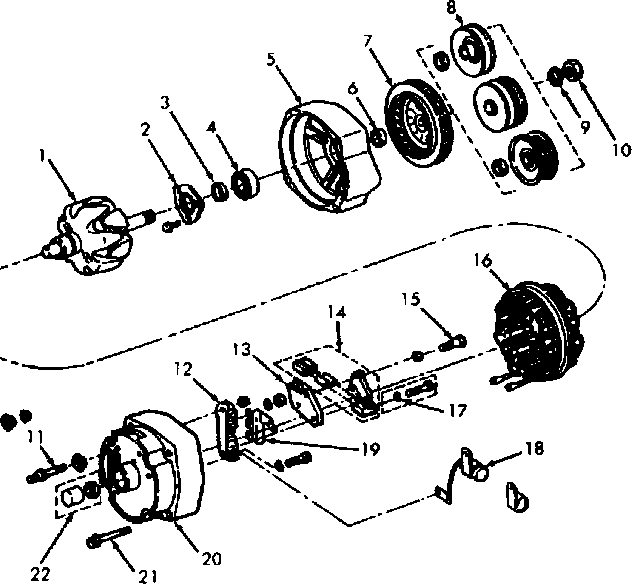
2 Front Bearing Retainer Plate
3. Inner Collar
4. Bearing
5. Front Housing
6. Inner Collar
7. Fan
8. Pulley
9 Lock Washer 10 Pulley Nut 11. Terminal Assembly 12 Bridge Rectifier
13. Regulator
14. Brush Assembly
15. Screw
16. Stator
17. insulating Washer
18. Capacitor
19. Diode Trio
20. Rear Housing
21. Through Bolt
22. Bearing & Seal Assembly
Fig. 3: Exploded View of SI Series Alternator
Courtesy of Chrysler M)tors.
TORQUE SPECIFICATIONS TABLE
Application Ft. Lbs. (N. nil
CS A1 t er nat or
Mmnt i ng Bolt ............................. 28 (38)
Power Steering M)unt i ng Bolt .............. 20 (27)
SI A1 t er nat or Grand Wgoneer
Adjusting Bolt .......................... 18 (24)
Pivot Bolt .............................. 33 (44)
W angler
Adjusting Bolt .......................... 20 (27)
A1 t er nat or -1 o-Br acket Bolt .............. 20 (27)
M)unt i ng Strap Bolt ..................... 20 (27)
Pivot Bolt or Nut ....................... 28 (38)
Pul 1 ey Nut .............................. 59 (81)