UNDERSTANDING THE FEATURES OF YOUR VEHICLE 51
Do not ride with the seatback reclined so that the shoulder belt is no longer resting against your chest. In a collision you could slide under the seat belt and be seriously or even fatally injured. Use the recliner only when the vehicle is parked.
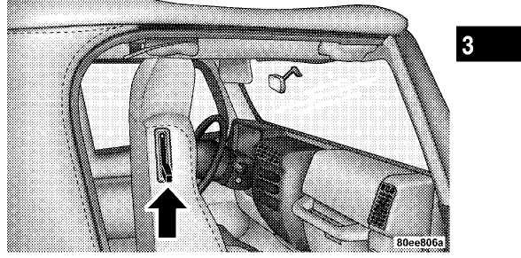
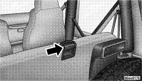
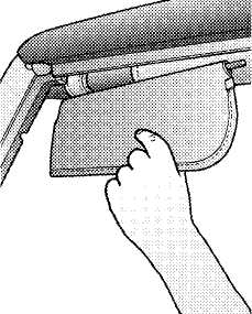
Tilting Front Seats
Push the lever upward on the seatback to tilt the entire seat forward.
52 UNDERSTANDING THE FEATURES OF YOUR VEHICLE
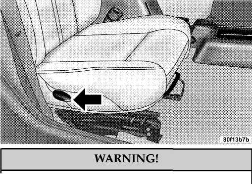
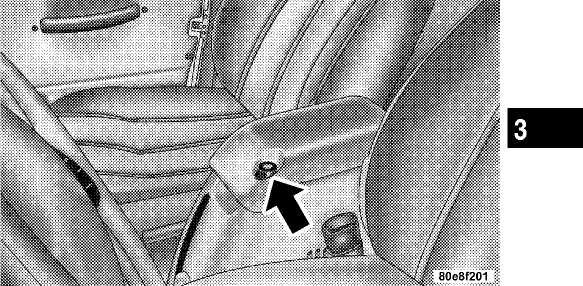
Fold
And Tumble Rear Seat
To expand the cargo area:
Slide
seat belts through the seat cushions into the
cargo area.
Lift
the seatback release lever and fold seatback for
ward.
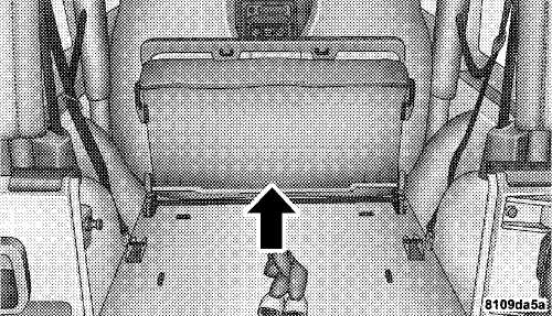
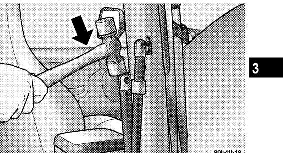
3. Slowly flip the entire seat forward.
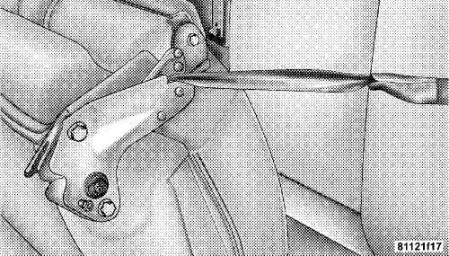
4. Secure the seat with the strap. Wrap strap around sport bar, and put one end of the strap through loop of the other end. Pull to tighten strap around sport bar. Place the opposite loop around hook of seat. Route the strap so that it is between the plates of the seat to eliminate slack and increase tension, as shown.
■ UNDERSTANDING THE FEATURES OF YOUR VEHICLE 53
Removing the Rear Seat
WARNING!
It
is extremely dangerous to ride in a cargo area,
inside or
outside of a vehicle. In a collision people
riding in these
areas are more likely to be seri
ously injured or killed.
Do not allow people to ride in any area of
your
vehicle that is not equipped with seats and seat
belts.
Be sure everyone in your vehicle is in a
seat and
using a seat belt properly.
5. When completed, return seat to it’s normal position.
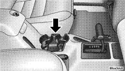
54 UNDERSTANDING THE FEATURES OF YOUR VEHICLE
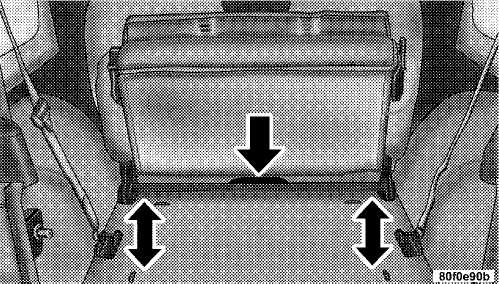
First
fold the rear seat forward following steps 1
through
3 under "Fold and Tumble Rear Seat"
in this
section.
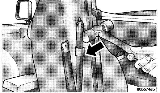
Press down on release bar on each side, and
pull seat
out and away from lower bracket.
Remove seat from the vehicle.
Replacing the Rear Seat
Reverse steps for removing the seat. Be certain to pull the seat belts between the seat cushion and seatback. Position them for passenger use.
WARNING!
To
help protect against personal injury, passen
gers should
not be seated in the rear cargo area
with the rear seat folded
down or removed from
the vehicle.
The rear cargo space is intended for load
carrying
purposes only, not for passengers, who should sit
in
seats and use seat belts.
UNDERSTANDING THE FEATURES OF YOUR VEHICLE 55
TO
OPEN AND CLOSE THE HOOD
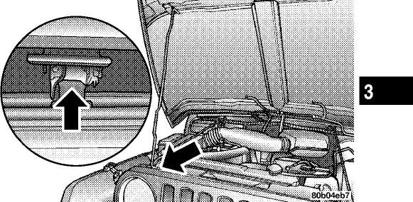
To open hood, first release both hood latches.
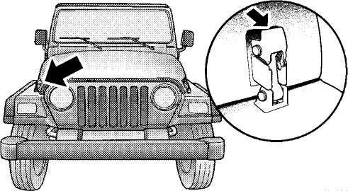
Next, locate handle in middle of the front end of the hood. Insert hand into gap between hood and radiator support and lift up on handle to raise hood. You may have to push down slightly on hood before lifting up on handle. Insert the support rod into the slot in the radiator support.
To close the hood, remove the support rod from the radiator support and place it in the retaining clip. Lower the hood slowly, then let it drop the last few inches. Secure both of the hood latches.
56 UNDERSTANDING THE FEATURES OF YOUR VEHICLE
WARNING!
If the hood is not fully latched, it could fly up when the vehicle is moving and block your forward vision. Be sure all hood latches are latched fully before driving.
LIGHTS
Interior Lights
The overhead light comes on when a door is opened. It may also be turned on by rotating the control for the dimmer switch on the muti-function control lever fully upward.
The overhead light will automatically turn off in about 20 minutes if a door is left open or the dimmer control is left in the dome light position. Turn the ignition switch ON to restore the overhead light operation.
Daytime Brightness Feature
Certain instrument panel components (odometer, radio display) can be illuminated at full brightness during the daytime. This can be helpful when driving with your headlights on during the daytime such as in a parade or a funeral procession. To activate this feature, rotate the left stalk one detent lower than the dome light.
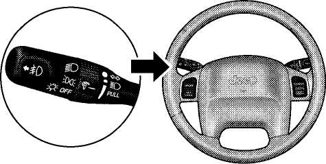
Multi-Function Control Lever
The multi-function control lever controls the operation of the parking lights, headlights, headlight beam selection, passing light, fog lights, instrument panel light dimming, and turn signals.
UNDERSTANDING THE FEATURES OF YOUR VEHICLE 57
Parking Lights, Instrument Panel Lights, and Headlights
Turn the end of the multi-function control lever to the first detent for parking lights and instrument panel lights. Turn to the second detent for headlight operation.
To change the brightness of the instrument panel lights, rotate the center portion of the muti-function control lever up or down.
NOTE: If the driver’s door is left open, and the headlights or parking lights are left on, the "High Beam Indicator Light" will flash and a chime will sound.
Lights-On Reminder
If the headlights or parking lights are on after the ignition is turned off, a chime will sound when the driver’s door is opened.
Headlight Dimmer Switch
Pull the multi-function control lever towards you to switch the headlights to HIGH beam. Pull the muti-function control lever a second time to switch the headlights to LOW beam.
Passing Light
You can signal another vehicle with your headlights by lightly pulling the multi-function control lever toward the steering wheel. This will cause the headlights to turn on at high beam and remain on until the lever is released.
58 UNDERSTANDING THE FEATURES OF YOUR VEHICLE
Front Fog Lights — If Equipped
The front fog light switch is in the multi-function control lever. To activate the front fog lights, turn on the parking or low beam headlights and pull out the end of the lever.
NOTE: The fog lights will only operate with the parking lights or the headlights on low beam. Selecting high beam headlights will turn off the fog lights.
Turn Signals
Move the multi-function control lever up or down and the arrows on each side of the instrument cluster flash to show proper operation of the front and rear turn signal lights. You can signal a lane change by moving the lever partially up or down without moving beyond the detent.
If either light remains on and does not flash, or there is a very fast flash rate, check for a defective outside light bulb. If an indicator fails to light when the lever is moved, it would suggest that the fuse or indicator bulb is defective.
NOTE: A tone will chime if the turn signals are left on for more than 1 mile (2 km).
Daytime Running Lights — Canada Only
The headlights come on at a low intensity level after the vehicle has been driven approximately 3 feet (1 meter). They will turn off when the vehicle is turned off or when the headlights are switched on.
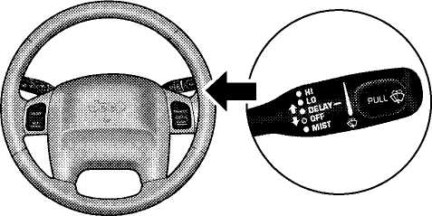
WINDSHIELD WIPERS AND WASHERS
CAUTION!
In cold weather, always turn off the wiper switch and allow the wipers to return to the park position before turning off the engine. If the wiper switch is left on and the wipers freeze to the windshield, damage to the wiper motor may occur when the vehicle is restarted.
Intermittent Wiper System
Use the intermittent wiper when weather conditions make a single wiping cycle, with a variable pause between cycles, desirable. Move the lever to the DELAY position, then select the delay interval by turning the end
UNDERSTANDING THE FEATURES OF YOUR VEHICLE 59
of the lever. The delay can be regulated from a maximum of approximately 18 seconds between cycles, to a cycle every second.
Windshield Wiper Operation
Move the lever upward to the second detent for LO speed wiper operation, or to the third detent for HI speed operation
Windshield Washers
To use the washer, pull the lever toward you and hold while spray is desired. If the lever is pulled while in the delay range, the wiper will operate for two wipe cycles after the lever is released, and then resume the intermittent interval previously selected.
If the lever is pulled while in the OFF position, the wipers will operate for as long as the lever is held plus two wipe cycles, then turn OFF.
Mist Feature
Push down on the wiper lever to activate a single wipe to clear off road mist or spray from a passing vehicle. As long as the lever is held down, the wipers will continue to operate.
60 UNDERSTANDING THE FEATURES OF YOUR VEHICLE
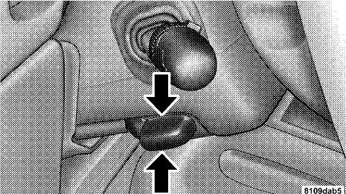
TILT STEERING COLUMN
To tilt the column, push down on the lever below the turn signal control and move the wheel up or down, as desired. Pull the lever back upwards to lock the column firmly in place.
WARNING!
Tilting the steering column while the vehicle is moving is dangerous. Without a stable steering column, you could lose control of the vehicle and have an accident. Adjust the column only while the vehicle is stopped. Be sure it is locked before driving.
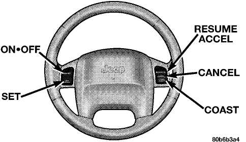
ELECTRONIC SPEED CONTROL
When engaged, this device takes over accelerator operations at speeds greater than 35 mph (60 km/h). The controls are mounted on the steering wheel and consist of ON-OFF, SET, RESUME/ACCEL, CANCEL, and COAST controls.
UNDERSTANDING THE FEATURES OF YOUR VEHICLE 61
To Activate
Press and release the ON-OFF button to turn the system on. To turn the system off, press the ON-OFF button again. The system should be turned off when not in use. The CRUISE indicator light in the instrument cluster illuminates when the system is on.
To Set At A Desired Speed
When the vehicle has reached the desired speed, press and release the SET button. Release the accelerator and the vehicle will operate at the selected speed.
To Deactivate
A soft tap on the brake pedal, normal braking, or pressing the CANCEL button will deactivate the Speed Control without erasing the memory. Pressing the ON-OFF button or turning off the ignition erases the memory.
To Resume Speed
To resume a previously set speed, press and release the RESUME/ACCEL button. Resume can be used at any speed above 30 mph (50 km/h).
To Vary The Speed Setting
When the Speed Control is on and set, speed can be increased by pressing and holding the RESUME/ACCEL button. When the button is released, a new set speed will be established.
Tapping the RESUME/ACCEL button once will result in a 2 mph (3 km/h) speed increase. Each time the button is tapped, speed increases, so tapping the button three times will increase speed by 6 mph (9 km/h), etc.
To decrease speed while speed control is on and set, press and hold the COAST button. Release the button when the desired speed is reached, and the new speed will be set.
62 UNDERSTANDING THE FEATURES OF YOUR VEHICLE
To Accelerate for Passing
Depress the accelerator as you would normally. When the pedal is released, the vehicle will return to the set speed.
NOTE: When driving uphill, at elevations above 2,000 ft. (610 meters), or when the vehicle is heavily loaded (especially when towing) the vehicle may slow below the SET speed. (If the vehicle speed drops below 30 mph (48 km/h), the Speed Control will automatically disengage). If this happens, you can push down on the accelerator pedal to maintain the desired speed.
WARNING!
Leaving the Speed Control on when not in use is dangerous. You could accidentally set the system or cause it to go faster than you want. You could lose control and have an accident. Always turn the system off when you are not using it.
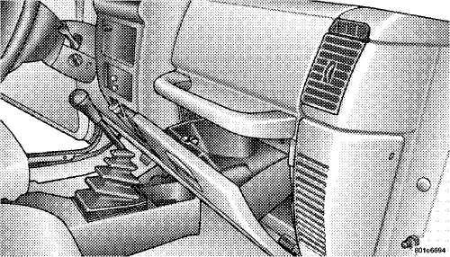
CIGAR LIGHTER AND ASHTRAYS — IF EQUIPPED
The vehicle may be equipped with a cigar lighter receptacle, element, and ashtray (Smoker’s Package Only). The cigar lighter will be located in the lower instrument panel (near the heater controls), and the removable ashtray will be located in the center console.

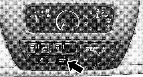
ELECTRICAL POWER OUTLET
To the right of the cigar lighter (if equipped) is the 12 volt power outlet. The outlet is connected directly to the battery, items plugged into this outlet may discharge the battery and/or prevent engine starting. The outlet includes a tethered cap labeled with a battery symbol indicating the power source.
■ UNDERSTANDING THE FEATURES OF YOUR VEHICLE 63
Electrical Outlet Use With Engine Off
WARNING!
Many
accessories that can be plugged in draw
power from the vehicle’s
battery, even when not
in use (i.e. cellular phones, etc.).
Eventually, if
plugged in long enough, the vehicle’s battery
will
discharge sufficiently to degrade battery
life
and/or prevent engine starting.
Accessories that draw higher power (i.e.
coolers,
vacuum cleaners, lights, etc.), will degrade the
battery
even more quickly. Only use these inter
mittently and with
greater caution.
After the use of high power draw
accessories, or
long periods of the vehicle not being started
(with
accessories still plugged in), the vehicle must be
driven
a sufficient length of time to allow the
alternator to recharge
the vehicle’s battery.
Power outlets are designed for accessory
plugs
only. Do not hang any type of accessory or acces
sory
bracket from the plug. Improper use of the
power outlet can cause
damage not covered by
your warranty.
64 UNDERSTANDING THE FEATURES OF YOUR VEHICLE
CUP HOLDERS The rear passengers have cup holders at the rear of the
 In
the center console there are two cup holders for the center
console, front seat passengers.
In
the center console there are two cup holders for the center
console, front seat passengers.
NOTE: The cup holder insert is removable from the console, for cleaning.
UNDERSTANDING THE FEATURES OF YOUR VEHICLE 65
STORAGE
Glove Compartment
To unlock the glove compartment, insert the key and turn. To open, pull the latch up.
Console Storage Compartment — If Equipped
To unlock, insert key and turn. To open, press the latch button.
Add-A-Trunk™ — If Equipped
The factory-installed Add-A-Trunk™ option provides a secured compartment for parcels or equipment when the tailgate is closed and locked. To gain access to this compartment, simply open the tailgate and release the spring loaded latch pins. The cover of the Add-A-Trunk™ can then be raised.
66 UNDERSTANDING THE FEATURES OF YOUR VEHICLE
When the Add-A-Trunk™ is not desired, it can be easily removed from the rear compartment. Remove the four knobs that secure the "trunk" to the body. Lift the Add-A-Trunk™ out and place the knobs in the molded-in storage area. Storage space is also provided for the wheel lock, and lock key tool.
Do not leave the Add-A-Trunk™ loose in your vehicle. Remove it and store it in a safe place.
DUAL TOP — IF EQUIPPED
If your vehicle is equipped with a Dual Top, you must remove one of the tops from the vehicle. The soft top was installed at the factory for shipping purposes only. The soft top and the hard top are to be used independently. Removal is mandatory to prevent any possible wear and tear on the soft top, should both tops remain on the vehicle at the same time. Failure to do so may void your soft top warranty.
Removing The Soft Top
1. Locate
and remove the 2 boxes that contain
the
following items:
right and left door frames
door frame attachment knobs (4)
right and left quarter windows
rear tailgate window
Remove
the hard top. Refer to "Hard Top Removal" in
this
section.
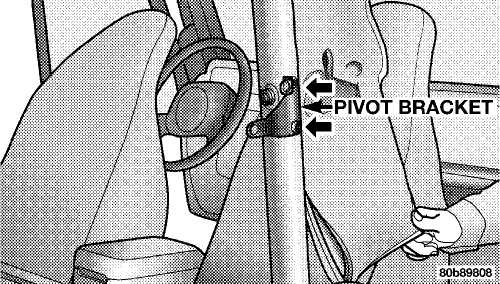
Remove
the soft top bow assembly pivot bracket
screws
(2 per side) using a #30 Torx®
head driver.
UNDERSTANDING THE FEATURES OF YOUR VEHICLE 67
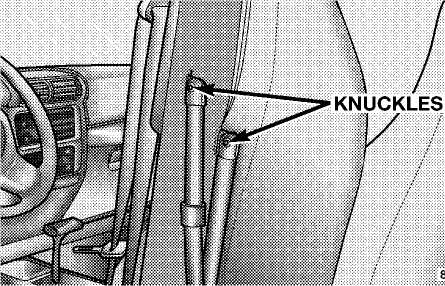
4.
Using a rubber mallet, carefully tap the knuckles
from the outside edge. This will remove
the bow assembly from the pivot bracket.
Remove the soft top from the vehicle and store in a clean, dry
location.
68 UNDERSTANDING THE FEATURES OF YOUR VEHICLE
5. Unzip the zipper on the sport bar cover to expose the pivot bracket. Remove the brackets using a #T40 Torx® head driver. Recover and re-zip the sports bar cover. Store pivot brackets and screws in a safe place.
6. Reinstall the hard top. Refer to "Hard Top Installation" in this section.
Installing the Soft Top
NOTE: The following procedures are for first time set up only. For future soft top procedures, refer to "Soft Top" in this section.
1. Locate
and remove the following items prior to hard
top
removal:
right and left door frames
door frame attachment knobs (4)
right and left quarter windows
rear tailgate window.
Remove
the hard top. Refer to "Hard Top Removal" in
this
section.
Install
the door frames. Refer to "Door Frame" in this
section.
If
the soft top has been removed, follow these steps to
reinstall
the soft top. If the soft top is on the vehicle,
proceed
to step #4.
a. If the
pivot brackets have been removed, unzip
the sport bar cover and
attach the pivot brackets and
screws with a #T40 Torx® head
driver. Re-cover and
re-zip sport bar cover.
b. If the
door frames have been removed, re-install
them (refer to "Door
Frame" in this section).
UNDERSTANDING THE FEATURES OF YOUR VEHICLE 69
c. Lay
the soft top back into the vehicle with the
curved portion of the
bows facing upward.
d. Tap
the knuckles on the side with a rubber mallet
to reattach them to
the pivot bracket.
e. Screw
the pivot screws back into place. Secure
them until they are snug
being careful not to cross-
thread the screws.
CAUTION!
Do not overtighten the screws. You can strip the screws if they are overtightened.
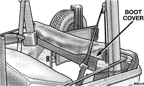
5. Unsnap and remove the black boot cover. This cover should be discarded. It was intended as a protective cover for shipping only.
NOTE: A visual instruction sheet is enclosed in the dual top wrap.
70 UNDERSTANDING THE FEATURES OF YOUR VEHICLE
Open
the tailgate.
Remove
the tailgate bar (black bar with end caps) that
is located in
the soft top and set aside.
NOTE: Be sure the wire harness is not attached to the soft top bows before you lift the top.
Lift
the soft top fabric up and away from the plastic
header with
latches.
Pull
all of the soft top fabric toward the rear of the
vehicle and
wrap around the plastic header.
Pull
the soft top fabric around the ends of the plastic
header so
that the fabric has a tight, smooth appearance.
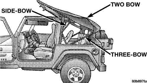
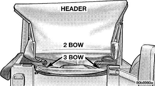
Working
from the rear of the vehicle with the tailgate
open,
lift the plastic header up and over the sport bar. As
the
header reaches the top, locate the 2 bow
and push it
up and over the sport bar.
UNDERSTANDING THE FEATURES OF YOUR VEHICLE 71
12. Move to the side of the vehicle and pull the side bow 13. Unclip and move the sun visor to the side, forward and down. You will see the 3 bow rise from the rear of the vehicle.