STARTING AND OPERATING
EXAMPLE:
Service Description:
95 = Load Index
—A numerical code associated with the maximum load a tire can carry.
H = Speed Symbol
—A symbol indicating the range of speeds at which a tire can carry a load corresponding
to its load index under certain operating conditions.
—The maximum speed corresponding to the Speed Symbol should only be achieved under specified operating conditions, (ie. tire pressure, vehicle loading, road conditions and
posted speed limits).
Load Identification:
"....blank...." = Absence of any text on sidewall of the tire indicates a Standard Load (SL) Tire
Extra Load (XL) = Extra Load (or Reinforced) Tire
 Light
Load = Light
Load Tire
Light
Load = Light
Load Tire
C,D,E = Load range associated with the maximum load a tire can carry at a specified pressure
Maximum Load — Maximum Load indicates the maximum load this tire is designed to carry.
Maximum Pressure —
Maximum Pressure indicates the maximum permissible
cold tire inflation pressure for this
tire.
STARTING AND OPERATING 187
Tire Identification Number (TIN) Look for the TIN on the outboard side of black sidewall
The TIN may be found on one or both sides of the tire tires as mounted on the vehicle. If the TIN is not found on
however the date code may only be on one side. Tires the outboard side then you will find it on the inboard side
with white sidewalls will have the full TIN
including of the tire,
date code located on the white sidewall
side of the tire.
EXAMPLE:
DOT MA L9 ABCD 0301
DOT = Department of Transportation _
—This symbol certifies that the tire is in compliance with the U.S. Department of Transportation tire I
safety standards, and is approved for highway use.
MA = Code representing the tire manufacturing location.(2 digits)
L9 = Code representing the tire size. (2 digits)
ABCD = Code used by tire manufacturer.(1 to 4 digits)
03 = Number representing the week in which the tire was manufactured. (2 digits)
—03 means the 3rd week.
01 = Number representing the year in which the tire was manufactured. (2 digits)
—01 means the year 2001.
—Prior
to July 2000, tire manufacturers were only
required to have 1 number to represent the
year in
which
the tire was manufactured. Example: 031 could
represent the 3rd week of
1981 or 1991.
188 STARTING AND OPERATING
Tire Loading and Tire Pressure Tire Placard Location
NOTE: The tire placard is located on the lower driver’s side instrument panel.
Tire and Loading Information Placard
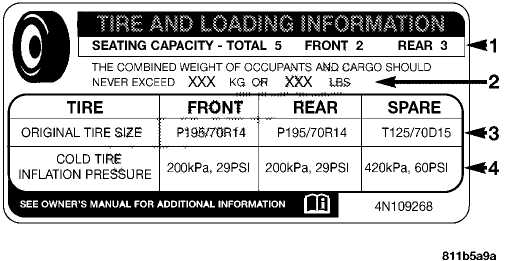
This placard tells you important information about the,
number of people that can be carried in the vehicle
the total weight your vehicle can carry
the tire size designed for your vehicle
the cold
tire inflation pressures for the front, rear
and spare tires.
Loading
The vehicle maximum load on the tire must not exceed the load carrying capacity of the tire on your vehicle. You will not exceed the tire’s load carrying capacity if you adhere to the loading conditions, tire size and cold tire inflation pressures specified on the Tire and Loading Information placard and the Vehicle Loading section of this manual.
NOTE: Under a maximum loaded vehicle condition, gross axle weight ratings (GAWR’s) for the front and rear axles must not be exceeded. For further information on GAWR’s, vehicle loading and trailer towing, see the Vehicle Loading section of this manual.
To determine the maximum loading conditions of your vehicle, locate the statement "The combined weight of occupants and cargo should never exceed XXX kg or XXX lbs." on the Tire and Loading Information placard. The
STARTING AND OPERATING 189
combined weight of occupants, cargo/luggage and trailer tongue weight (if applicable) should never exceed the weight referenced here.
Steps for Determining Correct Load Limit
Locate
the statement "The combined weight of occu
pants and
cargo should never exceed XXX pounds" on
your vehicle’s
placard.
Determine
the combined weight of the driver and
passengers that will be
riding in your vehicle.
Subtract
the combined weight of the driver and pas
sengers from XXX
kilograms or XXX pounds.
The
resulting figure equals the available amount of
cargo
and luggage load capacity. For example, if "XXX"
amount
equals 1400 lbs. and there will be five
150 lb.
passengers
in your vehicle, the amount of available cargo
and luggage load
capacity is 650 lb. (1400-750 (5 x
15) =
650 lb.)
determine
the combined weight of luggage and cargo
being loaded on the
vehicle. That weight may not safely
exceed
the available cargo and luggage load capacity
calculated
in step 4.
If
your vehicle will be towing a trailer, load from your
trailer
will be transferred to your vehicle. Consult this
manual to
determine how this reduces the available
cargo and luggage load
capacity of your vehicle.
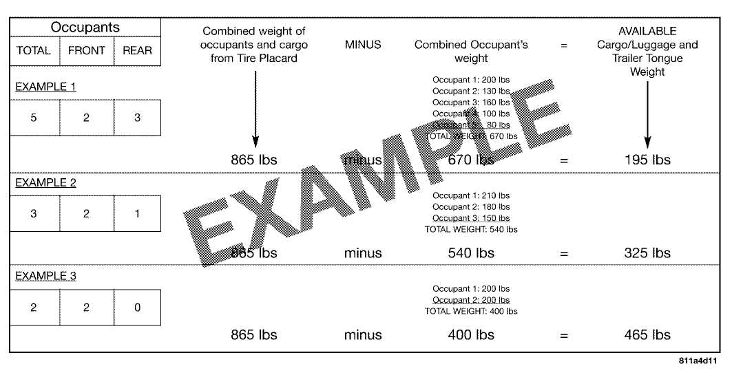
NOTE: The following table shows examples on how to calculate total load, cargo/luggage and towing capacities of your vehicle with varying seating configurations and number and size of occupants. This table is for illustration purposes only and may not be accurate for the seating and load carry capacity of your vehicle.
NOTE: For the following example the combined weight of occupants and cargo should never exceed 865 lbs. (392 Kg).
190 STARTING AND OPERATING
STARTING AND OPERATING 191
 WARNING!
1. Safety—

 Overloading
of your tire is dangerous. Overloading can cause tire failure,
affect vehicle handling, and increase your stopping distance. Use
tires of the recommended load capacity for your vehicle-never
overload them.
Overloading
of your tire is dangerous. Overloading can cause tire failure,
affect vehicle handling, and increase your stopping distance. Use
tires of the recommended load capacity for your vehicle-never
overload them.
TIRES
— GENERAL INFORMATION
Tire Pressure
Proper tire inflation pressure is essential to the safe and satisfactory operation of your vehicle. Three primary areas are affected by improper tire pressure:
WARNING!
Improperly
inflated tires are dangerous and can cause accidents.
Under
inflation increases tire flexing and can
result in tire failure.
Over
inflation reduces a tire’s ability to cushion
shock. Objects on
the road and chuck holes can cause
damage that results in tire
failure.
Unequal
tire pressures can cause steering prob
lems. You could lose
control of your vehicle.
Over
inflated or under inflated tires can affect
vehicle handling and
can fail suddenly, resulting in
loss of vehicle control.
Always drive with each tire inflated to the recommended pressure.
192 STARTING AND OPERATING
2. Economy—
Improper inflation pressures can cause uneven wear patterns to develop across the tire tread. These abnormal wear patterns will reduce tread life resulting in a need for earlier tire replacement. Under inflation also increases tire rolling resistance and results in higher fuel consumption.
3. Ride Comfort and Vehicle Stability—
Proper tire inflation contributes to a comfortable ride. Over inflation produces a jarring and uncomfortable ride. Both under inflation and over inflation affect the stability of the vehicle and can produce a feeling of sluggish response or over-responsiveness in the steering.
Unequal tire pressures can cause erratic and unpredictable steering response.
Unequal tire pressure from side to side may cause the vehicle to drift left or right.
Tire Inflation Pressures
The proper cold tire inflation pressure is located on the lower driver’s side instrument panel.
The tire pressure should be checked and adjusted at least once every month. Check more often if subject to a wide range of outdoor temperatures, as tire pressures vary with temperature changes.
Inflation pressures specified on the label are always "Cold Inflation Pressure." Cold inflation pressure is defined as the tire pressure after the vehicle has been idle for at least 3 hours, or driven less than a mile after a 3 hour period. The cold inflation pressure must not exceed the maximum values molded into the tire sidewall.
Tire pressures may increase from 13 to 40 kPa (2 to 6 psi) [0.138 to 0.414 bar] during operation. DO NOT reduce this normal pressure buildup.
STARTING AND OPERATING 193
High Speed Operation
Radial-Ply Tires
 WARNING!
WARNING!
High
speed driving with your vehicle under load is dangerous.
The added strain on your tires could cause
them to fail. You could have a serious accident. Don’t drive a
vehicle loaded to maximum capacity at continuous
speeds above 75 mph
(120 km/h).
Combining radial ply tires with other types of tires on your vehicle will cause your vehicle to handle poorly. The instability could cause an accident. Always use radial tires in sets of four. Never combine them with other types of tires.
The
manufacturer advocates driving at safe speeds within posted speed
limits. Where speed limits or conditions are such that the
vehicle can be driven at high speeds, correct tire inflation
pressure is very important.
Cuts and punctures in radial tires are repairable only in the tread area because of sidewall flexing. Consult your dealer for radial tire repairs.
Tire Spinning
When stuck in mud, sand, snow, or ice conditions, do not spin your vehicle’s wheels above 35 mph (55 km/h).
194 STARTING AND OPERATING

 WARNING!
Fast
spinning tires can be dangerous. Forces generated
by excessive wheel speeds may cause tire damage
or failure. A tire could explode and injure someone.
Do not spin your vehicle’s wheels faster than
35 mph (55km/h) when you are stuck. And
don’t let anyone near a spinning wheel, no
matter what the speed.
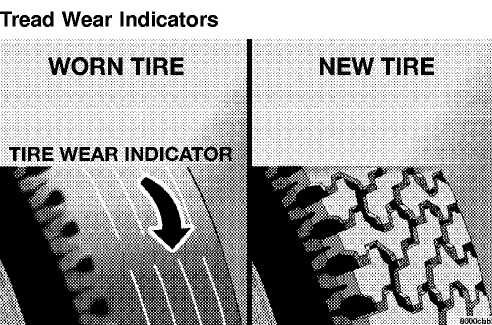
These indicators are narrow strips 1/16 inch (1.6 mm) thick and are found in the tread pattern grooves.
When the tread pattern is worn down to these treadwear indicators, the tires should be replaced.
Overloading your vehicle, long trips in very hot weather, and driving on bad roads may result in greater wear.
Replacement Tires
The tires on your new vehicle provide a balance of many characteristics. They should be inspected regularly for wear and correct inflation pressure. The manufacturer strongly recommends that you use tires equivalent to the originals in quality and performance when replacement is needed (see section on tread wear indicators). Failure to use equivalent replacement tires may adversely affect the safety, handling and ride of your vehicle. We recommend that you contact your original equipment tire dealer on any questions you may have on tire specifications or capability.
STARTING AND OPERATING 195

 WARNING!
CAUTION!
Do
not use a tire, wheel size or rating other than that
specified
for your vehicle. Some combinations of
unapproved tires and
wheels may change suspen
sion dimensions and performance
characteristics,
resulting in changes to steering, handling, and
brak
ing of your vehicle. This can cause
unpredictable
handling and stress to steering and suspension
com
ponents. You could lose control and have an
accident
resulting in serious injury or death. Use only the
tire
and wheel sizes with load ratings approved for
your
vehicle.
Never use a tire smaller than the minimum
tire size
listed on your vehicle’s tire label. Using a smaller
tire
could result in tire overloading and failure. You
could
lose control and have an accident.
Failure to equip your vehicle with tires
having
adequate speed capability can result in sudden
tire
failure and loss of vehicle control.
Overloading your tires is
dangerous. Overloading
can cause tire
failure. Use tires of the recommended
load
capacity for your vehicle - never
overload them.
Replacing original tires with tires of a different size may result in false speedometer and odometer readings. Check with your dealer before replacing tires with a different size.
Alignment
And Balance
Tire suspension components of your vehicle should be inspected and aligned when needed, to obtain maximum tire tread life.
Poor suspension alignment may result in:
reduced tread life;
uneven tire wear, such as feathering and
one-sided
wear,
vehicle pull to the right or to the left.
Tires may also cause your vehicle to pull to the left or right. Alignment won’t correct this condition. See your dealer for proper diagnosis.
196 STARTING AND OPERATING
Improper alignment will not cause vehicle vibration, which may be a result of tire and wheel out-of-balance. Proper balancing will reduce vibration and avoid tire cupping and spotty wear.
TIRE CHAINS
Install chains on rear tires only. Tire chains may be installed on all models except Sahara. Follow these recommendations to guard against damage and excessive tire and chain wear:
Use
chains on P205/75R15 or P215/75R15 tires only.
P225/75R15, LT30
x 9.50R15, and LT245/75R16 tires
do not provide adequate
clearance.
Use SAE class "S" tire chains or traction devices only.
Chains
must be the proper size for the vehicle, as
recommended by the
chain manufacturer.
Follow
tire chain manufacturer’s instructions for
mounting
chains.
Install
chains snugly and tighten after.6 mile (1 km)
of
driving.
Do not exceed 30 mph (48 km/h).
Drive
cautiously, avoiding large bumps, potholes and
extreme driving
maneuvers.
Do not
use chains or traction devices on the Poly-spare
tire.
TIRE ROTATION RECOMMENDATIONS
Tires on the front and rear axles of vehicles operate at different loads and perform different steering, handling, and braking functions. For these reasons, they wear at unequal rates, and develop irregular wear patterns.
These effects can be reduced by timely rotation of tires. The benefits of rotation are especially worthwhile with aggressive tread designs such as those on On/Off Road type tires. Rotation will increase tread life, help to maintain mud, snow, and wet traction levels, and contribute to a smooth, quiet ride.
STARTING AND OPERATING 197
Follow the recommended tire rotation frequency for your type of driving found in the "Maintenance Schedules" Section of this manual. More frequent rotation is permissible if desired. The reasons for any rapid or unusual wear should be corrected prior to rotation being performed.
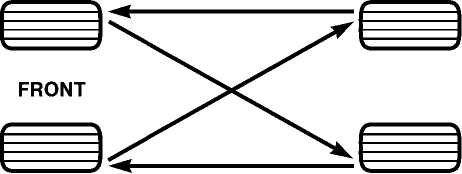
The suggested rotation method is the "forward-cross" shown in the following diagram.
FUEL REQUIREMENTS
„«Doc™,-™.! Your engine is designed to meet all emis-̣́́ïê» sions regulations and provide excellent fg fuel economy and performance when us-^^ ■ ing high quality unleaded gasoline having 8îî<èàüá an octane rating of 87. The use of premium gasoline is not recommended. The use of premium gasoline will provide no benefit over high quality regular gasoline, and in some circumstances may result in poorer performance.
Light spark knock at low engine speeds is not harmful to your engine. However, continued heavy spark knock at high speeds can cause damage and immediate service is required. Engine damage resulting from operation with a heavy spark knock may not be covered by the new vehicle warranty.
Poor quality gasoline can cause problems such as hard starting, stalling and hesitations. If you experience these symptoms, try another brand of gasoline before considering service for the vehicle.
198 STARTING AND OPERATING
 Over
40 auto
manufacturer’s world wide have issued and endorsed consistent
gasoline specifications (the Worldwide
Fuel Charter, WWFC) to define fuel properties necessary to deliver
enhanced emissions, performance, and
durability for your vehicle. The manufacturer recommends
the use of gasoline that meets the WWFC specifications
if they are available.
Over
40 auto
manufacturer’s world wide have issued and endorsed consistent
gasoline specifications (the Worldwide
Fuel Charter, WWFC) to define fuel properties necessary to deliver
enhanced emissions, performance, and
durability for your vehicle. The manufacturer recommends
the use of gasoline that meets the WWFC specifications
if they are available.
Reformulated Gasoline
Many areas of the country require the use of cleaner burning gasoline referred to as Reformulated Gasoline. Reformulated gasoline contains oxygenates, and is specifically blended to reduce vehicle emissions and improve air quality.
The manufacturer strongly supports the use of reformulated gasoline. Properly blended reformulated gasoline will provide excellent performance and durability for the engine and fuel system components.
Gasoline/Oxygenate Blends
Some fuel suppliers blend unleaded gasoline with oxygenates such as 10% ethanol, MTBE, and ETBE. Oxygenates are required in some areas of the country during the
winter months to reduce carbon monoxide emissions. Fuels blended with these oxygenates may be used in your vehicle.
CAUTION!
DO
NOT use gasoline containing METHANOL. Gasoline containing methanol
may damage critical fuel system components.
MMT
In Gasoline
MMT is a manganese containing metallic additive that is blended into some gasoline to increase octane. Gasoline blended with MMT provides no performance advantage beyond gasoline of the same octane number without MMT. Gasoline blended with MMT reduces spark plug life and reduces emission system performance in some vehicles. The manufacturer recommends that gasoline without MMT be used in your vehicle. The MMT content of gasoline may not be indicated on the gasoline pump, therefore, you should ask your gasoline retailer whether or not his/her gasoline contains MMT.
STARTING AND OPERATING 199
 It
is even more important to look for gasoline without MMT in Canada
because MMT can be used at levels higher than allowed in the United
States. MMT is prohibited in Federal and California
reformulated gasoline.
It
is even more important to look for gasoline without MMT in Canada
because MMT can be used at levels higher than allowed in the United
States. MMT is prohibited in Federal and California
reformulated gasoline.
Sulfur In Gasoline
If you live in the northeast United States, your vehicle may have been designed to meet California low emission standards with clean burning, low sulfur, California gasoline. Gasoline sold outside of California is permitted to have higher sulfur levels which may affect the performance of the vehicle’s catalytic converter. This may cause the "Malfunction Indicator Light" to illuminate.
Illumination of this light while operating on high sulfur gasoline does not necessarily mean your emission control system is malfunctioning. The manufacturer recommends that you try a different brand of unleaded gasoline having lower sulfur to determine if the problem is fuel related prior to returning your vehicle to an authorized dealer for service.
CAUTION!
If
the "Malfunction Indicator Light" is flashing, immediate
service is required. See "Onboard Diagnostic
System" in Section 7 of this manual.
Materials
Added To Fuel
All gasoline sold in the United States is required to contain effective detergent additives. Use of additional detergents or other additives is not needed under normal conditions.
200 STARTING AND OPERATING

FUEL
FILLER CAP (GAS CAP)
The fuel cap is located on the left side of the vehicle. If the fuel cap is lost or damaged, be sure the replacement cap is for use with this vehicle.
CAUTION!
Damage
to the fuel system or emission control system could result from
using an improper fuel cap (gas cap). A poorly fitting cap could let
impurities into the fuel system. Also, a poorly fitting after-market
cap can cause the MIL (Malfunction Indicator Light) to
illuminate, due to fuel vapors escaping from the system.
Turn
the engine off.
Rotate the fuel cap to the left to remove.
To replace the cap, insert it into the filler neck and tighten the cap about 1/4 turn until you hear one click. This is an indication that the cap is properly tightened.
Make sure that the fuel cap tether strap is not caught under the fuel cap.
STARTING AND OPERATING 201

 CAUTION!
WARNING!
To
avoid fuel spillage and overfilling, do not "top off" the
fuel tank after filling.
NOTE:
When the fuel nozzle "clicks" or shuts off, the fuel
tank is full.
Remove
the fuel cap (gas cap) slowly to prevent
fuel spray from the
filler neck which may cause
injury.
The
volatility of some gasoline may cause a
buildup of pressure in
the fuel tank that may
increase while you drive. This pressure
can result
in a spray of gasoline and/or vapors when the cap
is
removed from a hot vehicle. Removing the cap
slowly allows the
pressure to vent and prevents
fuel spray.
Never
have any smoking materials lit in or near
the vehicle when the
fuel cap is removed or the
tank filled.
Never
add fuel to the vehicle when the engine is
running.
202 STARTING AND OPERATING
 WARNING!
CAUTION!
A
fire may result if gasoline is pumped into a portable container that
is inside of a vehicle. You could be burned. Always place gas
containers on the ground while filling.
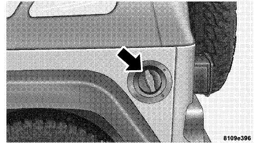
Locking
Fuel Filler Cap (Gas Cap) — If
Equipped
Turn the engine off.
Insert
the ignition key into the fuel cap, and turn the
key to the
right to unlock the fuel cap. Rotate the fuel
cap to the left to
remove.
To
replace the cap, insert it into the filler neck and
tighten
the cap about 1/4 turn until you hear one
click.
This is an indication that the cap is properly tightened.
Make
sure that the fuel cap tether strap is not caught
under the fuel
cap.
Be sure to remove the key.
’top
To avoid fuel spillage and overfilling, do not off" the fuel tank after filling.
NOTE:
When the fuel nozzle "clicks" or shuts off, the fuel
tank is full.
TRAILER TOWING
In this section you will find information on limits to the type of towing you can reasonably do with your vehicle. Before towing a trailer, carefully review this information to tow your load as efficiently and safely as possible.
To maintain warranty coverage, follow the requirements and recommendations in this manual concerning vehicles used for trailer towing.
Perform maintenance services as prescribed in the "Maintenance Schedules" section. When your vehicle is used for trailer towing, never exceed the gross axle weight rating (GAWR) by the addition of:
• The tongue weight of the trailer.
STARTING AND OPERATING 203
• The
weight of any other type of cargo or equipment
put
in or on your vehicle.
Remember that everything put in or on the trailer adds to the load on your vehicle.
Warranty Requirements
The manufacturer’s warranty will apply to vehicles used to tow trailers for noncommercial use, however the following conditions must be met:
The "D" Overdrive range can be
selected when tow
ing. However, if frequent shifting occurs
move the
shift lever to the next lower position to
eliminate
excessive automatic transmission shifting. This
action
will also reduce the possibility of transmission
over
heating and provide better engine braking. Refer
to
"Transmission Shifting" in this section for
additional
information.
A load equalizing hitch is
recommended for loaded
trailer weights
above 1,000 lbs (454 kg).
CAUTION!
If
the trailer weighs more than 1,000 lbs
(454 kg) loaded,
it should have its own brakes and they should
be of adequate capacity. Failure to do this could
lead to accelerated brake lining wear, higher brake
pedal effort, and longer stopping distances.
WARNING!
Connecting
trailer brakes to your vehicle’s hydraulic brake lines can overload
your brake system and cause it to fail. You might not have brakes
when you need them and could have an accident.
Whenever
you pull a trailer, regardless of the trailer size, stop lights and
turn signals on the trailer are mandatory for motoring safety.
Follow the maintenance intervals in schedule "B" for changing the automatic transmission fluid and filter, if you REGULARLY tow a trailer for more than 45 minutes of continuous operation.
204 STARTING AND OPERATING
Minimum Vehicle Requirements for Trailer Towing
|
Trailer Type |
Gross Trailer Weight |
Tongue Weight (Sec Note 1) |
Towing Package |
GCWR (Max.) (See Note 2) |
Engine |
Transmission |
Cooling |
Axle |
|
Fold Down and Low Profile • 25 ft2 (2.3m2) ˆh©-^ or Less Frontal Area • Up to 2,000 Ibs. (907 kg) (also small boats flatbed trailers, etc.) |
1,000 lbs. (453 kg) (Max.) |
10to 15% Of GTW 300 lbs. (Max) |
Class 1 Hitch |
5,350 lbs. (2,247 kg) |
2.4 L |
ALL |
ALL |
ALL |
|
|
2,000 Ibs. (907 kg) (Max} |
|
Class 1 Hitch |
6,250 Ibs. (2,835 kg) |
4.0 L |
ALL |
ALL |
ALL |
|
|
3,500 Ibs. (1587 kg) (Max.) |
|
Class 2 Hitch (Unlimited Models Only) |
8,100 Ibs. (3,674 kg) (Unlimited Models Only) |
4.0 L |
ALL |
ALL |
ALL |
|
Other Trailer Types and Weights up to Full Box Shape •
Up
to 64 ft2 , ÷ •
Up
to 5,000 Ibs. f S. • Maximum Travel ( ) Trailer Length 25 ft. (7.6m) 1—@®—•= |
NOT RECOMMENDED |
|||||||
The
towing vehicle payload should be reduced by the tongue load (for a
dead weight hitch) to keep the rear axle loading below
GAWR
(Gross Axle Weight Rating) of 2,650 Ibs.
(1,204 kg).
GCWR= Total combined weight of trailer and tow vehicle.
812C8573
STARTING AND OPERATING 205

 NOTE:
Refer
to "Recommended Fluids, Lubricants, and
Genuine Parts" in Section 7
for
axle differential lubrication specifications for towing.
NOTE:
Refer
to "Recommended Fluids, Lubricants, and
Genuine Parts" in Section 7
for
axle differential lubrication specifications for towing.
SNOW PLOW
Snow plows should not be added to the front end of your vehicle.
RECREATIONAL TOWING (BEHIND MOTORHOME, ETC.)
Shifting Into Neutral (N)
Use the following procedure to prepare your vehicle for recreational towing.
CAUTION!
It
is necessary to follow these steps to be certain that the
transfer case is fully in N (Neutral)
before recreational towing to prevent
damage to internal parts.
CAUTION!
Internal
damage to the transfer case will occur if a front or rear wheel lift
is used when recreational towing.
NOTE:
The transfer case must be shifted
into N (Neutral) for recreational
towing.
Depress brake pedal.
Shift
automatic transmission into N (Neutral)
or de
press clutch pedal on
manual transmission.
Shift transfer case lever into N (Neutral).
Start engine.
Shift
automatic transmission into D (Drive) or manual
transmission
into gear.
206 STARTING AND OPERATING
 Release
brake pedal and ensure that there is no vehicle
Release
brake pedal and ensure that there is no vehicle
movement.
Shut
the engine off and place the ignition key into the
unlocked OFF
position.
Shift automatic transmission into P (Park).
Apply parking brake.
Attach vehicle to the tow vehicle with tow bar.
Release parking brake.
CAUTION!
Shifting Out Of Neutral (N)
Use the following procedure to prepare your vehicle for normal usage.
Shift
automatic transmission into N (Neutral)
or de
press clutch pedal on
manual transmission.
Shift transfer case lever into desired position.
Shift
automatic transmission into D (Drive) or release
clutch on
manual transmissions.
NOTE: When shifting out of transfer case N (Neutral) on automatic transmission equipped vehicles, turning the engine off may be required to avoid gear clash.
Damage
to the transmission may occur if the transmission is shifted
into P (Park) with the transfer case in N
(Neutral) and the engine running. With the
transfer case in N
(Neutral) ensure that the engine is off
prior to shifting the transmission into P (Park) (refer
to steps 7-8 above).
STARTING AND OPERATING
WARNING!
CAUTION!
You or others could be injured if you leave the vehicle unattended with the transfer case in the N (Neutral) position without first fully engaging the parking brake. The transfer case N (Neutral) position disengages both the front and rear driveshafts from the powertrain and will allow the vehicle to move despite the transmission position. The parking brake should always be applied when the driver is not in the vehicle.
• Do not use a bumper mounted clamp-on tow bar on your vehicle. The bumper face bar will be damaged.