| CONDITION | POSSIBLE CAUSE | CORRECTION |
FLUID DISCOLORED OR SMELLS VEHICLE DOES NOT MOVE IN
DELAYED 1 -2.2-3 OR 3-OD DRAG OR BIND ON 1-2,2-3
| Fluid contaminated Shift linkage out of adjustment Electronic control problem
| Replace fluid Disassemble and repair transmission Adjust linkage Find fauhv part with DRBir Tester * Repair with DRBlI Tester * |
SERVICE DIAGNOSIS (CONT.)
| CONDITION | POSSIBLE CAUSE | CORRECTION |
| HARSH DOWN-SHIFT NO OOWN-SWiFT WHEN coasting DOWN-SHIFT LATE OR EARLY DURMG COAST NOOD-3.3-2OR2-1 KICKDOWN NO ENGINE 8RAUNG H 1-2 POSITION VEHICLE DOES NOT HOLD IN PARK | Throttlle coble out of adjustment Throttlle cable and cam faulty Accumulator pistons faulty Valve body faulty Transmission faulty Volve body faulty Solenoid faulty Electronic control problem Throttle cable faulty Valve body faulty Transmission faulty Solenoid faulty Electronic control problem Solenoid bully Electronic control problem Valve body faulty Solenoid faulty Electronic control problem Valve body faulty Transmission faulty Shifl linkage out of adjustment Parking lock pawl cam and spring faulty | Adjust cable Replace cable and cam Repair pistons Repair valve body Disassemble and repair transmission Repair valve body Replace solenoid Locale problem with DRBir Tester * Replace cable Repair valve body Disassemble and repair transmission Replace solenoid Locale problem with DRBir Tester * Replace solenoid Locate problem with DRBII" Tester* Repair valve body Replace solenoid Locale problem with DRBII" Tester * Repair valve body Disassemble ond repair transmission Adjust linkage Replace cam ond spring |
* or Snap-On Scanner, OTC Scanner
CHECKING TRANSMISSION FLUID LEVEL AND CONDITION
Recommended Fluid
Recommended fluid for AW 4 transmissions is Jeep or Mopar Mercon"' automatic transmission fluid. Mopar Dexron Ď™ may also be used if Mercon fluid is not available.
Cheeking Fluid Level
Be sure transmission fluid is at normal operating
temperature. Normal operating temperature is reached
after approximately IS miles (25 km) of operation.
Position the vehicle on a level surface. This is
important for an accurate fluid level check.
Shift the transmission through all gear ranges and
back to Neutral.
Apply the parking brakes.
Verify that the transmission is in Neutral.
Wipe off the dipstick handle to prevent dirt from
entering the fill tube. Then remove the dipstick and
check fluid level and condition.
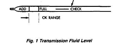
Correct fluid level is to the FULL mark on the
dipstick when the fluid is at normal operating tem
perature (Fig. 1).
If fluid level is low, top off the level with Jeep
Mercon", transmission fluid. Mopar Dexron II™ may
also be used if Mercon is not available. Do not overfill
the transmission. Add only enough fluid to bring
the level to the FULL mark.
TRANSMISSION
Cheeking Fluid Condition
Inspect the appearance of the fluid during the fluid level check. The fluid should be clear and free of foreign material or particles. If the fluid is dark brown or black in color and smells burnt, the fluid has been overheated and should be replaced.
Transmission operation should also be checked if the fluid is severely discolored and contains quantities of foreign material, metal particles, or clutch disc friction material.
A small quantity of friction material or metal particles in the oil pan is normal. The particles are usually generated during the break-in period and indicate normal seating of the various transmission components.
TCU SERVICE
Use the DRBII tester to diagnose TCU function when ever a fault is suspected. Replace the TCU only when the tqjter indicates a TCU fault.
TCU Replacement
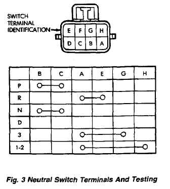
The TCU is located under the instrument panel on the passenger side of the vehicle (Fig. 2). Turn the ignition off. Remove the TCU by unsnapping the wire harness connector and removing the TCU from under the instrument panel. To install the replacement part, snap the wire harness connector into the new TCU and position it under the panel.
NEUTRAL SWITCH
Switch Testing
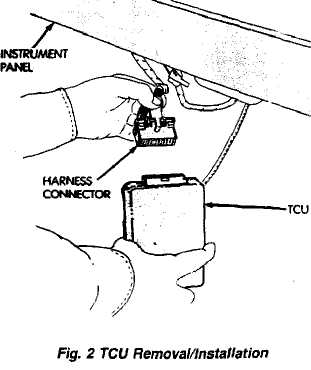
Test switch continuity with an ohmmeter. Disconnect the switch and check continuity at the connector terminal positions and in the gear ranges indicated in Figure 3. Switch continuity should be as follows:
Continuity should exist between terminals  and Ń
with the transmission in Park and Neutral only (Fig. ).
Continuity should exist between terminals A and E
with the transmission in Reverse (Fig. 3).
.
Continuity should exist between terminals A and G
with the the transmission in third gear (Fig. 3).
Continuity should exist between terminals A and H
with the transmission in first and/or second gear (Fig.
3).
Continuity should not exist in D position.
Neutral SwHtcH Removal
Raise vehide.
Disconnect switch wire harness connector.
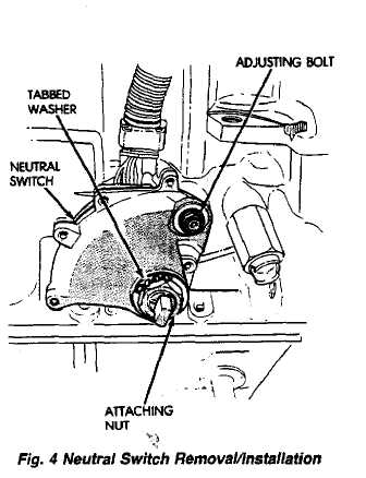
Pry washer lock tabs upward and remove switch
attaching not and tabbed washer (Fig. 4).
Remove switch adjusting bolt (Fig. 4).
(5) Slide switch off manual valve shaft.
Neutral Switch Installation And Adjustment
Disconnect shift linkage rod from shift lever on left
side of transmission.
Rotate manual shift lever all the way rearward.
Then rotate lever forward two detent positions to Neu
tral.
Install switch on manual valve shaft and install
switch adjusting bolt finger tight. Do not tighten bolt at
this time.
Install tabbed washer on manual valve shaft and
install switch attaching nut. Tighten nut to 6.9 ąm (61
in-lbs) torque but do not bend washer lock tabs over nut
at this time.
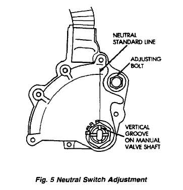
Verify that transmission is in Neutral.
Rotate switch to align neutral standard line with
vertical groove on manual valve shaft (Fig. 5).
Align switch standard line with groove or flat on
manual valve shaft.
Tighten switch adjusting bolt to 13 ąm (9 ft-lbs)
torque.
(9) Bend at least two washer lock tabs over switch
attaching nut to secure it.
Connect shift linkage rod to shift lever on left side
of case.
Connect switch wires to harness and lower ve
hicle.
Check switch operation. Engine should start in
Park and Neutral only.
VALVE BODY SOLENOIDS
Solenoid Removal And Testing
Remove transmission oil pan drain plug and drain fluid. (2! Remove pan bolts and remove oil pan.
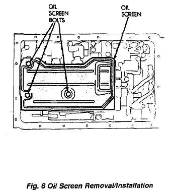
Remove oil screen bolts and remove screen (Fig. 6)
and gasket. Discard the gasket.
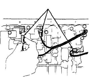
Disconnect solenoid wire connector (Fig. 7).
If all solenoids are being removed, mark or tag
wires for assembly reference before disconnecting them.
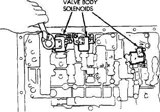
Remove bolt attaching solenoids to valve body and
remove solenoids (Fig. 8). Do not allow any valve body components to fall out when solenoids are removed.
Clean oil filter and pan with solvent and dry with
compressed air.
Remove old sealer material from oil pan and trans
mission case.
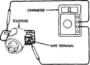
Solenoid Testing
Test solenoid resistance with an ohmmeter.
Connect the ohmmeter leads to the solenoid mounting bracket and to the solenoid wire terminal (Fig. 9).
Solenoid resistance should be 11-15 ohms.
Replace the solenoid if resistance is above or below the specified range.
Solenoid Installation
Position solenoids on valve body and install sole
noid bolts. Tighten bolts to 10 N«m (7 ft-lbs) torque.
Connect feed wires to solenoids.
Fig. 8 Valve Body Solenoids
Fig. 7 Solenoid Wire Connectors
SOLENOID WIRE CONNECTORS
Install new gaskets on oil screen and install
screen. Tighten screen bolts to 10 ąm (7 ft-lbs) torque.
Apply bead of Three-Bond ŇÂ 1281 or equivalent
sealer to oil pan sealing surface. Sealer bead should be
at least 1.0 mm (.040 in) wide,
Install oil pan on transmission. Tighten pan bolts
to 7.4 N-m (65 in-lbs) torque.
Install and tighten oil pan drain plug to 20 N-m (15
ft-lbs) torque.
Fill transmission with Mopar Mercon™ or Dexron
Ď™ transmission fluid.
Solenoid Harness Adapter Seal Replacement
Remove oil pan and oil screen. Refer to Solenoid
Removal procedure.
Disconnect solenoid wire connectors (Fig. 7).
Remove bracket securing solenoid harness adaptor
(Fig. 10) to case.
Pull harness adapter and wires out of case.
Remove and discard adapter O-ring.
Lubricate new O-ring and install it on adapter.
Install solenoid wire harness and adapter in case.
Install adapter bracket and bracket bolt.
Connect wires to solenoids.
(10) Install oil screen and oil pan.
VALVE BODY
Removal and installation are the only valve body service procedures covered in this section. Refer to the transmission overhaul section for valve body disassembly, cleaning, inspection and reassembly.
Valve Body Removal
Remove oil pan plug and drain transmission fluid.
Remove oil pan and oil screen. Clean pan and
screen in solvent and dry them with compressed air.
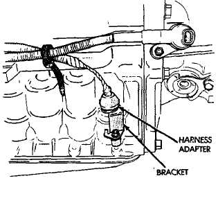
Fin 10 Harness Adantt*r Removal/Installation
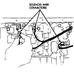
Disconnect solenoid wire connectors (Fig. 7). Mark
wires for assembly reference.
Remove valve body oil tubes <Fig. 13). Carefully
pry tubes out of valve body with screwdriver.
Disconnect throttle cable from throttle cam (Fig.
13).
Remove valve body bolts. Locations for seventeen
bolts are outlined in Figure 14.
Lower valve body and remove overdrive clutch
accumulator springs; direct clutch accumulator spring
and spacer; second brake accumulator spring and
spacer (Fig. 15)
Remove valve body and check ball and spring (Fig.
16).
Fig. 9 Testing Valve Body Solenoid
Fig. 11 Disconnect Solenoid Wires
Valve Body Installation
U) Connect cable to throttle cam (Fig. 13).
Install check ball and spring (Fig. 16).
Position accumulator springs and spacers on valve
body.
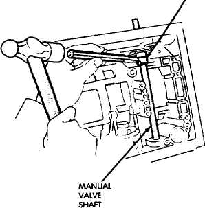
Align valve body manual valve with shift sector
(Fig. 17) and carefully position valve body on case.
Install valve body bolts (Fig. 14). Tighten bolts
evenly to 10 ąm (7 ft-lbs) torque.
Install valve body oil tubes. Be sure tube ends (L)
and (M) are installed as shown in Figure 18.
Remove old sealer material from oil pan and trans
mission case.
Clean oil screen and oil pan with solvent (if not
done previously). Dry both components with com
pressed air only. Do not use shop towels.
(9) Install hew gaskets on oil screen and install screen
on case. Tighten screen attaching bolts to 10 ąň (7
ft-lbs) torque.
Apply bead of Three Bond ŇÂ 1281 sealer to
sealing surface of oil pan. Sealer bead should be at least
1.0 mm (.040 in) wide. Then install oil pan and tighten
pan bolts to 7.4 ąm (65 in-lbs) torque.
Install new gasket on oil pan drain plug and
install plug in pan. Tighten plug to 20 Nin (15 ft-lbs)
torque.
Fill transmission with Mopar Mereon" fluid.
MANUAL VALVE SHAFT SEAL REPLACEMENT
(1) Remove neutral safety switch and disconnect transmission shift lever.
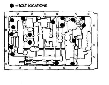 Fig. 14 Valve Body Bolt Locations
Fig. 12 Removing Valve Body Oil Tubes
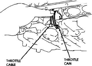

Fig. 13 Removing/Installing Throttle Cable
Fig. IS Accumulator Springs
Remove oil pan and valve body.
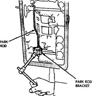
Remove bolts attaching park rod bracket to case
(Fig. 20).
Remove park rod from shift sector (Fig. 21),
Cut spacer sleeve with chisel and remove it from
manual valve shaft (Fig. 22).
Remove pin from shaft and sector with pin punch.
Remove shaft and sector from case.
Pry shaft seals out of case (Fig. 23).
Inspect the manual valve shaft and sector. Replace
either component if worn or damaged.
Coat replacement shaft seals with petroleum jelly
and seat them in the case (Fig. 24).
Install new spacer sleeve on sector (Fig. 25).
Lubricate manual valve shaft and install it in
case.
Lubricate sector and sleeve and install them on
shaft.
Align hole in spacer sleeve with notch in sector.
Then install shift sector roll pin. Tap pin into sector and
shaft and stake sleeve to sector and shaft securely.
(15) Connect park rod to sector (Fig. 21).
(16) Install park rod bracket (Fig. 26i Tighten
bracket bolts to 10 N-m (7 ft-lbs) torque.
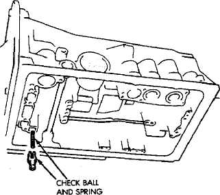
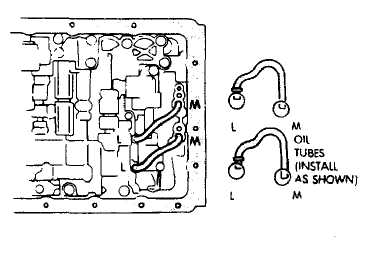
Fig. 16 Removing/Installing Valve Body Check Ball And Spring
Fig. 18 Installing Valve Body Oil Tubes
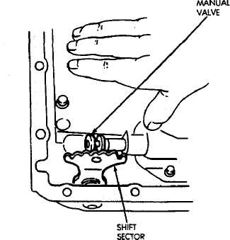
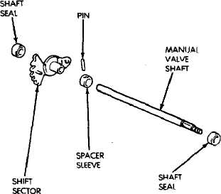
Fig. 17 Align Shift Sector And Manual Valve
Fig. 19 Manual Valve Shaft And Seals
(17) Install valve body, oil screen, oil pan and neutral switch.
THROTTLE CABLE REPLACEMENT-ADJUSTMENT
Throttle Cable Removal
In engine compartment, disconnect cable from
throttle linkage. Then compress cable mounting ears
and remove cable from linkage bracket.
Raise vehicle.
Remove transmission oil pan.
Disengage cable from throttle valve cam (Fig. 27).
Remove cable bracket bolt and remove cable and
bracket from case (Fig. 28).
Remove and discard cable seal.
Throttle Cable Installation
Lubricate and install new seal on cable.
Insert cable in transmission case.
Attach cable to throttle cam (Fig. 27).
Install cable bracket on case and tighten attaching
bolt to 10 N-m (7 ft-lbs) torque (Fig. 28).
SPACER
Fig, 20 Removing/Installing Park Rod Bracket
Fig. 22 Cutting Spacer Sleeve
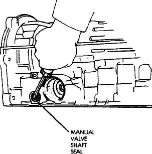
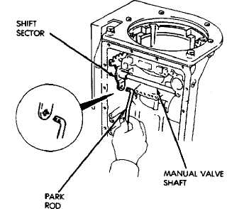
Fig. 21 Removing/Installing Park Rod
Fig. 23 Removing Manual Valve Shaft Seals
Remove old sealer material from oil pan and trans
mission case. Clean oil pan with solvent and dry it with
compressed air.
Apply bead of Three Bond ŇÂ 1281 sealer to oil pan
sealing surface. Sealer bead should be at least 1.0 mm
(.040 in) wide. Then install pan and tighten pan bolts to
7.4 ąm (65 in-lbs) torque.
Install new gasket on oil pan drain plug. Install
and tighten plug to 20 N-m (15 ft-lbs) torque.
Connect cable to engine bracket and throttle link
age.
Fill transmission with Mopar Mercon™.
(10) Adjust the cable as outlined in the Line Pressure Cable Adjustment procedure.