OVERDRIVE PLANETARY GEAR AND CLUTCH OVERHAUL
Gear And Clutch Disassembly
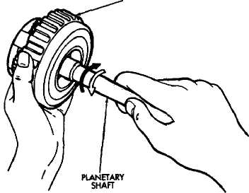
Check operation of one-way clutch in clutch drum.
Hold drum and turn planetary shaft clockwise and
counterclockwise. Shaft should turn clockwise freely
but lock when turned counterclockwise. Replace one
way clutch if necessary.
Remove overdrive clutch from planetary gear (Pig.
3).
Remove thrust bearing and race assembly from
clutch drum (Fig. 4).
Measure stroke length of clutch piston as follows:
(a) Mount oil pump on torque converter. Then mount clutch on oil pump (Fig. 5).
(b) Mount dial indicator on clutch and position
indicator stylus on clutch piston (Fig. 6).
(c) Apply compressed air through clutch feed hole
in oil pump and note piston stroke length. Stroke
length should be 1.85 to 2.15 mm (.0728 to .0846 in).
Replace clutch pack retainer if stroke length is
incorrect.Refer to chart in Specifications section for re
placement retainer thicknesses.
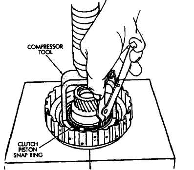
Remove clutch pack snap ring and remove the
clutch pack.
Compress piston return spring with tool B.Vi. FM.
27 and shop press and remove piston snap ring (Fig. 8).
Remove compressor tool and piston return springs.
Mount oil pump on converter. Then mount clutch
on oil pump (Fig. 9).
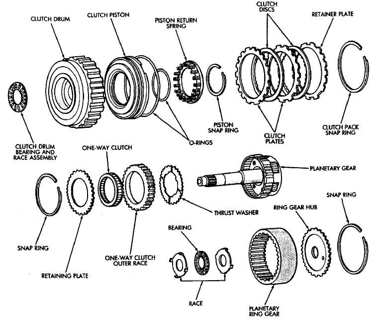
Fig. 1 Overdrive Planetary Gear And Clutch Components
Hold clutch piston by hand and apply compressed
air through oil pump feed hole to ease piston out (Fig.
9). Apply only enough air pressure to remove piston.
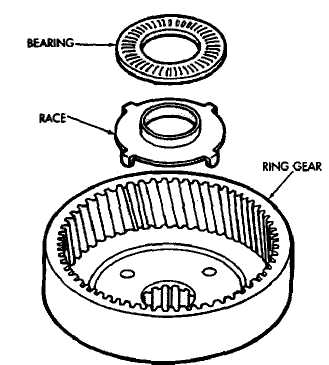
Remove bearing and race from ring gear (Fig. 10).
Remove snap ring from ring gear and remove ring
gear hub (Fig. 11).
Remove race from planetary gear (Fig. 12).
Remove snap ring and remove retaining plate
(Tig. 13).
Remove one-way clutch and outer race as assem
bly. Then separate race from clutch (Fig. 14).
Remove thrust washer (Fig. IS).
Measure clutch disc thickness. Minimum allow
able thickness is 1.84 mm (.0724 in).
CLUTCH DRUM
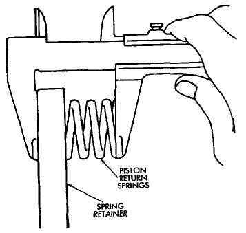
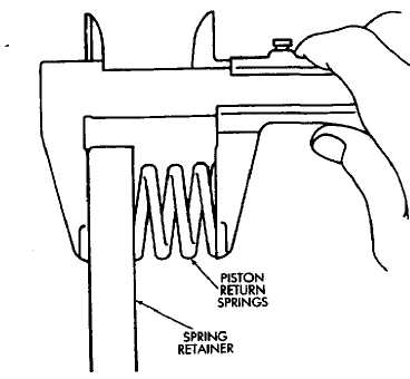
Measure free length of piston return springs with
springs in retainer (Fig. 16>. Length should be 16.8 mm
(.661 in).
Check clutch piston check ball (Fig. 17). Shake
piston to see if ball moves freely. Then check ball seal
ing by applying low pressure compressed air to ball inlet
as shown. Air should not leak past check ball.
Check inside diameter of clutch drum bushings
with bore gauge (Fig. 18). Maximum inside diameter is
27.11 mm (1.0673 in). Replace drum if bushing inside
diameter is greater than specified.
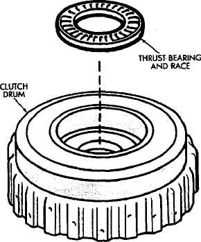
Fig. 4 Removing Clutch Drum Bearing And Race
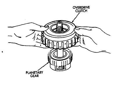
Fig. 2 Checking One-Way Clutch
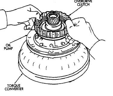
Fig. 3 Removing Overdrive Clutch From Gear
Fig. 5 Assembling Converter, Pump And Clutch For T
(21) Check inside diameter of planetary gear bushing (Fig, 19). Maximum inside diameter is 11.27 rom (0.4437 in). Replace planetary gear if bushing inside diameter is greater then specified.
Gear And Clutch Assembly
Install thrust washer in planetary gear (Fig. 20).
Grooved side of washer faces up and toward front.
Install one-way clutch in race (Fig. 21). Flanged
side of clutch must face upward as shown.
Install assembled one-way clutch and outer race in
planetary gear. Be sure flanged side of clutch is facing
upward.
Install clutch pack retaining plate and snap ring
in planetary gear.
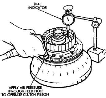
Fig. 8 Removing Clutch Piston Snap Ring
Coat planetary race with petroleum jelly and in
stall it on planetary gear. Outside diameter of race is
41.8 mm (1.646 in); inside diameter is 27.1 mm (1.067
in).
Install hub in planetary ring gear and install snap
ring.
Coat race and bearing with petroleum jelly and
install in planetary ring gear (Fig. 22).
Verify bearing/race size. Outside diameter of race
is 47.8 mm (1.882 in); inside diameter is 24.2 mm (.953
in). Outside diameter of bearing is 46.8 mm (1.843 in);
inside diameter is 26 mm (1.024 in).
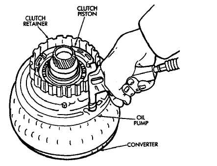
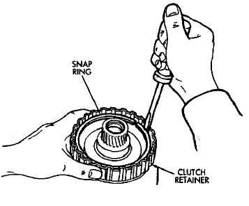
Fig. 6 Checking Overdrive Clutch Piston Stroke
Fig. 9 Removing Overdrive Clutch Piston
Fig. 7 Removing Clutch Pack Snap Ring 46 Fig. 9 Removing Overdrive Clutch Piston(9) Lubricate and install new O-rings on clutch piston.
Then install piston in clutch drum.
(10) Install piston return springs in clutch piston (Fig.
23).
Install piston snap ring. Compress piston return
springs with compressor tool and shop press (Fig. 24).
Install clutch pack in drum. Install steel plate
first, then a disc (Fig. 25). Continue installation se
quence until required number of discs and plates have
been installed.
Install clutch pack retainer with flat side facing
downward. Then install retainer snap ring (Fig. 26).
Compress springs with tool B.Vi. FM. 27.
Measure clutch piston stroke length again (refer
to procedure outlined in disassembly procedure ). If
stroke length is incorrect, install new clutch discs or
select fit retainer. Retainer thicknesses are outlined in
the Specifications section.
Install clutch drum bearing and race assembly
(Fig. 27). Be sure bearing rollers face upward as shown.
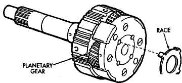
Fig. 10 Removing Ring Gear Bearing And Race
Fig. 12 Remove Planetary Gear Race
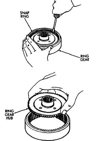
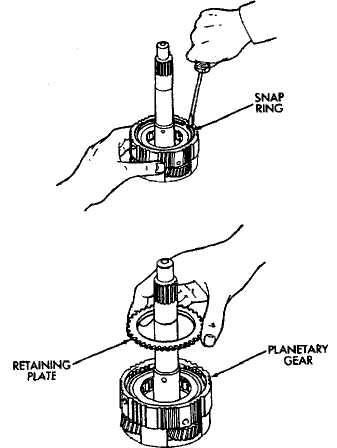
Fig. 11 Removing Ring Gear Hub
Fig. 13 Removing Snap Ring And Retaining Plate
Outside diameter of assembled bearing and race is 50.2 mm (1.976 in). Inside diameter is 28.9 mm (1.138 in). (16) Install clutch on planetary gear.
(17) Verify one-way clutch operation. Hold drum and turn planetary shaft clockwise and counterclockwise. Shaft should turn clockwise freely but lock when turned counterclockwise.
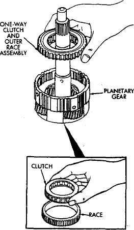
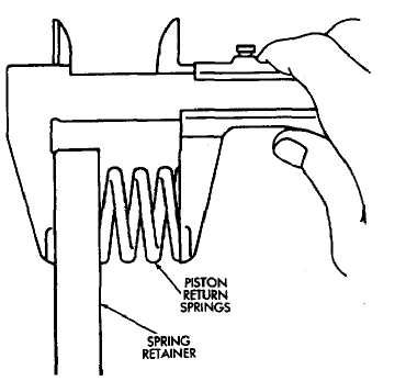
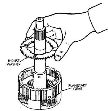
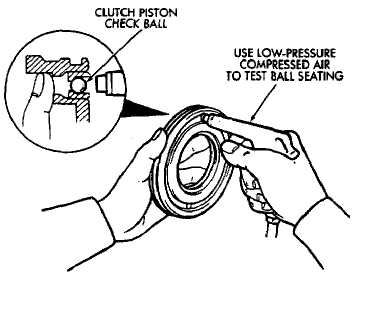
Fig. 14 Removing One-Way Clutch
Fig. 16 Checking Piston Return Spring Length
Fig. 17 Testing Clutch Piston Check Ball
Fig. 15 Removing Planetary Thrust Washer
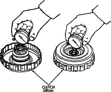
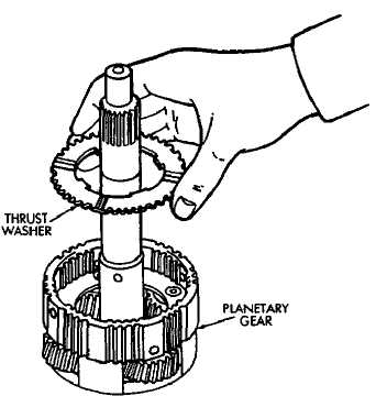
Fig. 18 Checking Clutch Drum Bushings
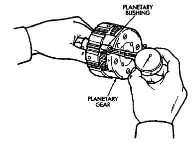
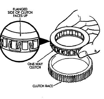
Fig. 19 Checking Planetary Bushing
Fig. 20 Install Planetary Thrust Washer
Fig. 21 Assembling One-Way Clutch And Race
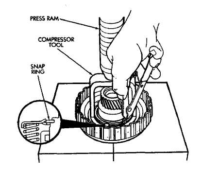
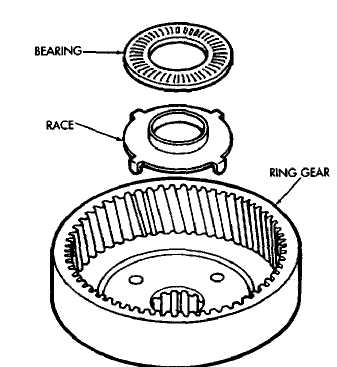
Fig. 24 Installing Clutch Piston Snap Ring
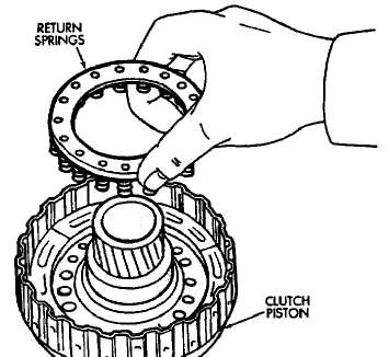 Fig. 22 Install Ring Gear Bearing And Race
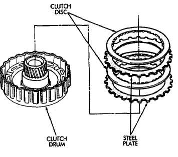
Fig. 23 Installing Piston Return Springs
Fig. 25 Installing Clutch Discs And Plates
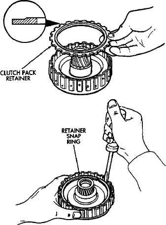
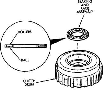
Fig. 27 Installing Clutch Drum Bearing And Race Assembly
Fig. 26 Installing Retainer And Snap Ring
OVERDRIVE SUPPORT OVERHAUL
Support Disassembly
Check brake piston operation. Mount support on
clutch (Fig. 2).
Apply compressed air through support feed hole
and observe brake piston movement (Fig. 2). Piston
should move smoothly and not bind or stick. If operation
is incorrect, replace piston and support.
Remove thrust bearing front race, thrust bearing
and rear race (Fig. 3).
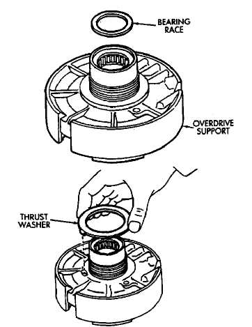
Turn overdrive support over and remove bearing
race and clutch drum thrust washer (Fig. 4).
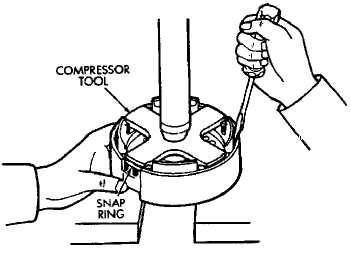
Compress piston return spring with tool B.Vi. FM.
26 and remove piston snap ring (Fig. 5).
Mount support in direct clutch and remove brake
piston with compressed air. Apply air to same feed hole
used when checking piston operation.
Remove and discard support O-rings (Fig. 1).
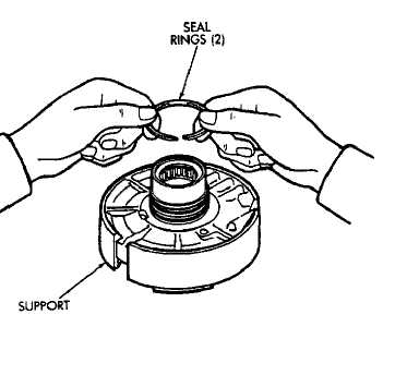
Remove support seal rings (Fig. 6).
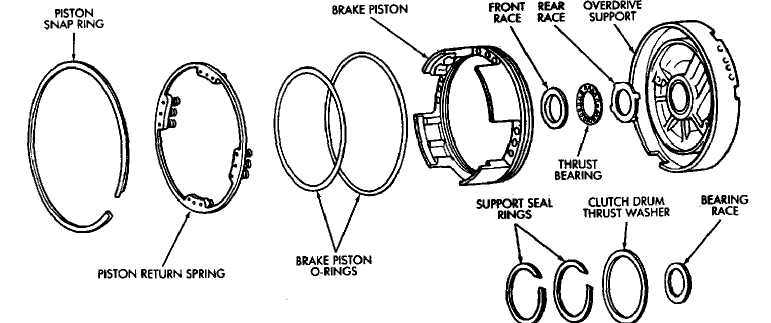
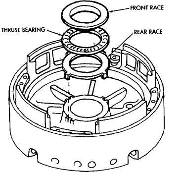 Fig. 1 Overdrive Support Components
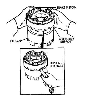
Fig. 2 Checking Brake Piston Movement
Fig. 3 Removing Support Thrust Bearing And Races
(9) Measure free length of piston return springs with
springs mounted in retainer (Fig. 7). Length should be
18.61 mm (.733 in).
Clean support components and dry them with
compressed air.
Inspect overdrive support and brake piston. Re
place support and piston if either part is worn or dam-
Fig. 4 Removing Clutch Drum Thrust Washer And Ďŕńĺ
Assembling Overdrive Support
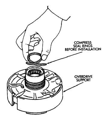
Lubricate new support seal rings. Then compress
rings and install them on support {Fig. 8).
Lubricate and install new O-rings on brake piston.
Then carefully seat piston in support.
Install return springs on brake piston.
Fig. 6 Removing Support Seal Rings
Compress return springs with tool (Fig. 5) and
install piston snap ring.
Install support bearing race and clutch drum
thrust washer (Fig. 4).
Install thrust bearing and front and rear bearing
races. Thrust bearing rollers should face upward as
shown (Fig. 9).
Fig. 7 Checking Piston Return Spring Lengtn
Fig. S Removing/Installing Piston Snap Ring 53 Fig. 7 Checking Piston Return Spring Length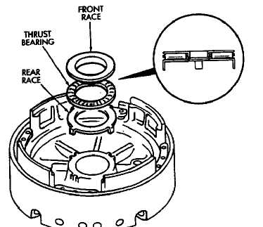
(7) Verify thrust bearing/race sizes (Fig. 9). Front race outer diameter is 47.8 mm (1.882 in); inside diameter is 30.7 mm (1.209 in). Rear race outer diameter is 47.8 mm
(1.882 in); inside diameter is 34.3 mm (1.350 in). Bearing outer diameter is 47.7 mm (1.878 in); inside diameter is 32.7 mm (1.287 in).
(8) Verify brake piston operation. Use same procedure described at beginning of disassembly. Piston should operate smoothly and not bind or stick.
Fig. 8 Installing Support Seal Rings
Fig. 9 Installing Support Thrust Bearing And Races
DIRECT CLUTCH OVERHAUL
Clutch Disassembly
(DRemove direct clutch from forward clutch (Fig. 2). (2) Remove clutch drum thrust washer (Fig. 3).

Fig. 1 Direct Clutch Components
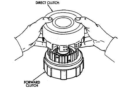
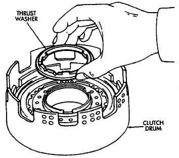
Fig. 3 Removing Clutch Drum Thrust Washer
Fig. 2 Separate Direct Clutch From Forward Clutch 55 Fig. 3 Removing Clutch Drum Thrust WasherCheck clutch piston stroke length as outlined in
following steps.
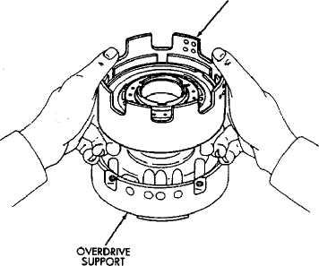
Mount direct clutch on overdrive support assembly
(Fig. 41.
Mount dial indicator on clutch and position indi
cator plunger on clutch piston (Fig. 4).
Apply 57-114 psi air pressure through feed hole in
overdrive support and note piston stroke length iFig. 5).
Check stroke at least twice.
Piston stroke length should be 1.37 mm to 1.60 mm
(.0539 to .0642 in). If stroke length is incorrect, either
the clutch pack retainer or clutch discs will have to be
replaced.
DIRECT ClUTCH
Compress clutch springs with tool B.Vi. FM. 27.
Remove clutch pack snap ring and remove retainer and
clutch pack from drum (Fig. 6).
Compress clutch piston return springs with tool
B.Vi. FM. 27 and remove clutch piston snap ring (Fig.
7).
Remove compressor tool and return spring.
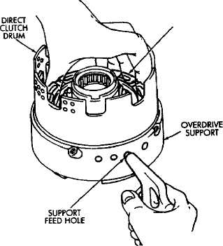
Remove clutch piston. Remount clutch on over
drive support (Fig. 8). Apply compressed air through
piston feed hole in support to remove piston. Use only
enough air to ease piston out.
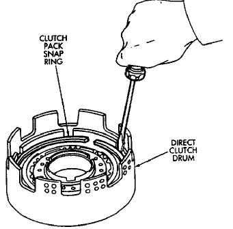
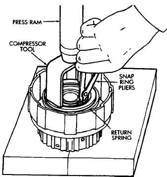
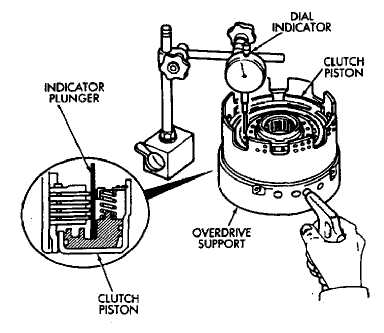
Fig. 4 Mount Direct Clutch On Overdrive Support
Fig. 6 Removing Clutch Pack Snap Ring
Fig. 5 Checking Direct Clutch Piston Stroke Length
Fig. 7 Removing Piston Return Spring Snap Ring
CLUTCH PISTON
Fig. 8 Removing Direct Clutch Piston
Remove and discard clutch piston O-rings.
Measure clutch disc thickness. Minimum allow
able thickness is 1.84 mm (.0724 in). Replace discs if
below minimum thickness.
Measure free length of piston return springs with
springs in retainer (Fig. 9). Length should be 21.32 mm
(.839 in). Replace return springs if not within specifi
cation.
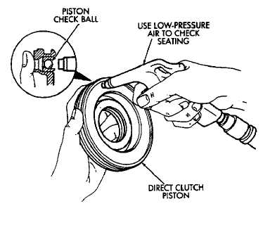
Check clutch piston check ball (Fig. 10). Shake
piston to see if ball moves freely. Then check ball seat
ing by applying low pressure compressed air to ball inlet
as shown. Air should not leak past check ball.
(16) Measure inside diameter of clutch drum bushing. Inside diameter should be no more than 53.97 mm (2.1248 in). Replace drum if bushing inside diameter is greater than specified.
Direct Clutch Assembly
Lubricate and install replacement O-rings on
clutch piston.
Install clutch piston in drum and install return
springs on piston.
Compress piston return springs and install snap
ring (Fig. 7). Be sure snap ring end gap is not aligned
with spring retainer tab.
Install clutch discs and plates (Fig. 11). Install
plate then disc until all plates and discs are installed.
Use four plates and discs in 6-cyl. transmissions and
three plates and discs in 4-cyl. transmissions.
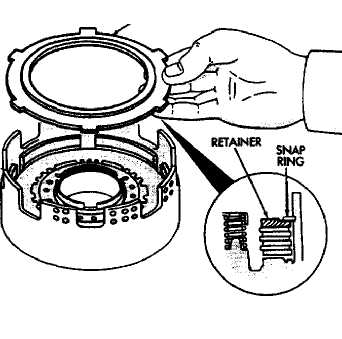
Install clutch pack retainer in drum (Fig. 12).
Install clutch pack snap ring (Fig. 12).
Check snap ring position. If necessary, shift snap
ring until end gap is not aligned with any notches in
clutch drum (Fig. 12).
Check clutch piston stroke length a second time.
If length is OK, continue with assembly. If stroke length
is incorrect, replace clutch discs or use different thick
ness clutch pack retainer (Fig. 12). See Specifications
section for retainer thicknesses.
Lubricate clutch drum thrust washer with petro
leum jelly and install it in drum (Fig. 3).
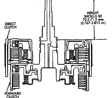
Mount direct clutch assembly on forward clutch
assembly and check assembled height (Fig. 14). Height
should be 70.3 to 71.5 mm (2.767 to 2.815 in).
If assembled height is incorrect, clutches are not
seated.
Fig. 9 Checking Piston Return Spring Length
Fig. 10 Testing Piston Check Ball Seating
(12) If clutch height is OK, remove direct clutch from forward clutch and proceed to forward clutch overhaul.
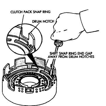
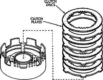
Fig. 11 Installing Direct Clutch Discs And Plates
Fig. 13 Adjusting Clutch Pack Snap Ring Position
CLUTCH PACK ’RETAINER
Fig. 12 Install Clutch Pack Retainer
Fig. 14 Checking Direct Clutch Assembled Height
FORWARD CLUTCH OVERHAUL
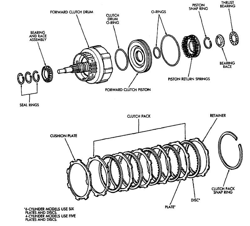
Fig. 1 Forward Clutch Components
59
Forward Clutch Disassembly
(1) Check clutch piston stroke as outlined in following
steps.
Position overdrive support on wood blocks and
mount forward clutch drum on support (Fig. 2).
Remove bearing and race from forward clutch
drum (Fig. 2).
(4) Mount dial indicator on clutch drum. Position dial
indicator plunger against clutch piston (Fig. 3).
THRUST BEARING BEARING RACE
Fig. 2 Positioning Drum And Support On Wood Blocks
Apply compressed air through right side feed hole
in support and note piston stroke length on dial indi
cator.
Stroke length should be: 3.73 to 4.59 mm (.1469 to
.1807 in) on 6-cyl. transmissions and 3.42 to 4.23 mm
(.1346 to .1665 in) on 4-cyl. transmissions.
Replace clutch discs if stroke length is incorrect.
Remove clutch pack snap ring and remove retainer
and clutch pack (Fig. 4).
Remove clutch pack cushion plate (Fig. 5).
Compress clutch springs with tool B.Vi. FM. 27
and remove piston snap ring.
Remove spring compressor tool and piston return
springs.
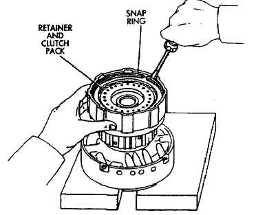
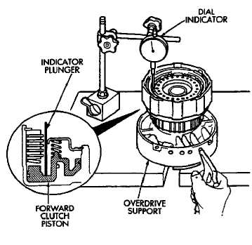
Fig. 4 Removing Retainer And Clutch Pack
CUSHION PLATE
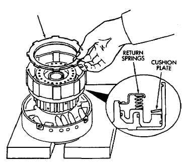
Fig. 3 Checking Forward Clutch Piston Stroke Length
Fig. 5 Removing Cushion Plate