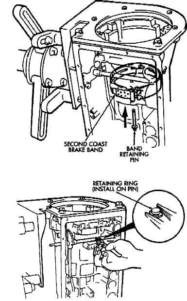
Fig. 23 Installing Band Retaining Pin
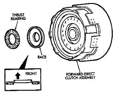
Fig. 24 Installing Forward-Direct Clutch Thrust Bearing And Race
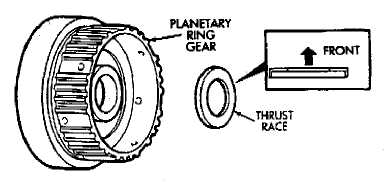
Fig. 25 Installing Planetary Ring Gear Race
(b) Apply and release brake piston with compressed air. Apply air pressure through feed hole in ease (Fig. 44).
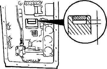
(.c) Piston stroke length should be 1.32 to 1.62 mm (.052 to .063 in) on 4-cyl. transmissions and 1.40 to 1.70 mm (.55 to .66 in) on 6-cyl. transmissions.
(d) If stroke is incorrect, brake pack or piston is
installed incorrectly. Check and correct as necessary
and measure piston stroke again.
Remove dial indicator and gauge tool.
Remove overdrive brake piston snap ring and
remove overdrive clutch pack components.
Coat overdrive lower race, thrust bearing and
upper race with petroleum jelly and install them in
overdrive support (Fig. 45). Be sure races and bearing
are assembled and installed as shown.
(56) Verify bearing/race sizes before proceeding.
Bearing-race sizes are: Outer diameter of lower race is
47.8 mm (1.882 in); inside diameter is 34.3 mm (1.350
in). Outer diameter of bearing is 47.7 mm (1.É78 in); inside diameter is 32.7 mm (1.287 in). Outer diameter of upper race is 47.8 mm (1,882 in); inside diameter is 30.7 mm (1.209 in).
Install overdrive planetary ring gear in support
(Fig. 46).
Coat ring gear thrust race and thrust bearing
assembly with petroleum jelly and install them in gear
(Fig. 47).
Verify bearing/race size before proceeding. Outer
diameter of ring gear race-bearing is 47.8 mm (1.882
in); inside diameter is 24.2 mm (0.953 inl. Outer diam
eter of bearing (61) is 46,8 mm (1.S44 ini; inside diam
eter is 26.0 mm (1.024 in).
Coat tabbed thrust race with petroleum jelly and
install it on planetary gear (Fig. 48). Race outer diam
eter is 41.8 mm (1.646 in); inside diameter is 27.1 mm
(1.067 in).
Coat thrust bearing and race assembly with pe
troleum jelly and install it on clutch input shaft (Fig.

Fig. 28 Installing Ring Gear Bearing And Race
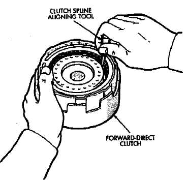
Fig. 26 Aligning Forward-Direct Clutch Splines
50J. Bearing and race outer diameter is 50.2 mm (1.976 in); inside diameter is 28.9 mm (1.138 in). (63) Install overdrive brake pack as follows: -
Install 4.0 mm (.157 in) thick plate first.
Rounded edge of plate must face upward.
Install a disc followed by a plate until the
required number of discs and plates are installed. Be
sure to install the stepped plate last with the flat side
of the plate facing the disc (Fig. 51).
Install four discs and three plates in 6-cyl.
transmissions. Install three discs and two plates in
4-cyl. transmissions.
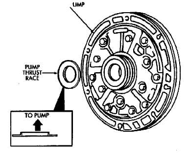
Coat thrust bearing race with petroleum jelly and
install it in oil pump (Fig. 53). Bearing race outer di
ameter is 47.2 mm (1.858 in); inside diameter is 28.1
mm (1-106 in).
Lubricate and install replacement O-ring on oil
pump body.
Install oil pump in case. Align pump and case bolt
holes and carefully ease pump into place (Fig. 54).
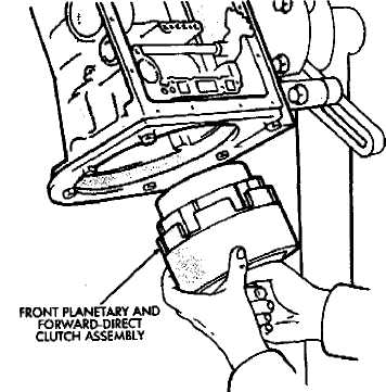
Fig. 29 Installing Front Planetary And Forward-Direct Clutch Assembly

Fig. 27 Installing Front Planetary Ring Gear
CAUTION: Do not use force to seat the pump. The seal rings on the stator shaft could be damaged if they bind or stick to the direct clutch drum.
Tighten oil pump bolts to 22 N-m (16 ft-lbs)
torque.
Verify input shaft rotation. Shaft should rotate
smoothly and not bind.
Lubricate and install new 0-ring on throttle ca
ble adapter and install cable in case (Fig. 55).
(71) Check clutch and brake operation. Operate
clutches and brakes with compressed air applied
through feed holes in case (Fig. 56). Listen for clutch
and brake application. If you do not hear a clutch or
brake apply, disassemble transmission and repair fault
before proceeding. It is necessary to block the over-
drive clutch accumulator feed hole No. 8 (Fig. 56) in order to check direct clutch operation.
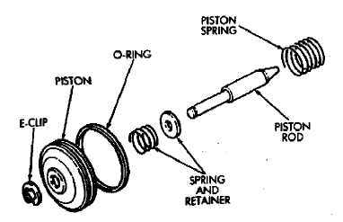
Fig. 32 Assembling Second Coast Brake Piston
CLEARANCE SHOULD BE: 9 8-11.8 mm (0.384-0.465 in.)
Fig. 30 Checking Input Drum-To-Oirect Clutch Drum Clearance
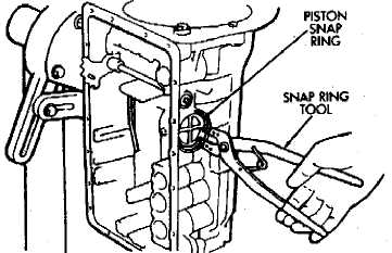

Fig. 31 Installing Clutch Shaft Thrust Bearing-Race Assembly
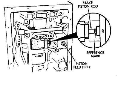
Fig. 34 Marking Brake Piston Rod
Lubricate and install new O-rings on accumula
tor pistons (Fig. 57).
Assemble and install accumulator piston compo
nents (Fig. 57). Refer to Accumulator Component Iden
tification Chart in Specifications section for piston,
spring and pin sizes.
Install new check ball body and spring (Pig. 58).
Position valve body on case (Fig. 59).
Install detent spring (Fig. 59).
Align manual valve, detent spring and shift sec
tor (Fig. 59).
Connect throttle cable to throttle valve cam (Fig.
60).
Install and tighten valve body-to-case bolts to 10
N-m (7 ft-lbs) torque.
Connect valve body solenoid wires to solenoids
(Fig. 61).
Install new O-ring on solenoid harness adapter
and secure adapter to case.
Install valve body oil tubes (Fig. 62). Tap tubes
into place with a plastic mallet. Be sure the flanged tube
ends and straight tube ends are installed as shown.
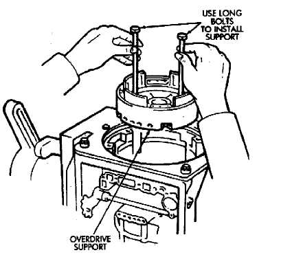
Fig. 37 Installing Overdrive Support 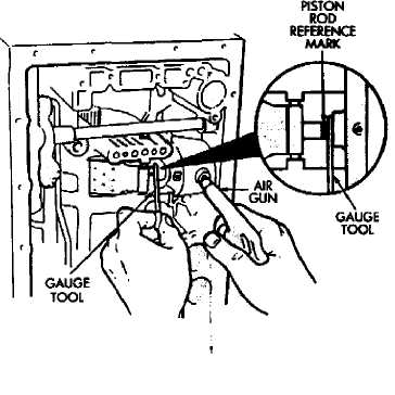
Fig. 35 Checking Second Coast Brake Piston Stroke

Fig. 36 Installing Overdrive Support Thrust Race And Washer
OVERDRIVE SUPPORT
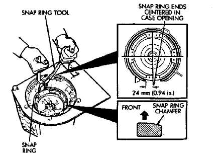
Fig. 38 Installing Overdrive Support Snap Ring
(83) Install new gaskets on oil screen and install screen on valve body. Tighten screen bolts to 10 ąň 7 ft-lbs) torque.

Fig. 39 Installing Overdrive Support Bolts
DIAL
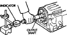
Fig. 40 Checking Output Shaft End Play
Install magnet in oil pan. Be sure magnet does
not interfere with valve body oil tubes.
Apply Three-Bond ŇÂ 1281 or equivalent sealer,
to sealing surface of oil pan. Sealer bead should be at
least 1 mm (.040 in) wide. Install pan on case and
tighten pan bolts to 7-4 N-m (65 in-lbs) torque.
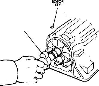
Install speed sensor rotor and key on output shaft
(Fig. 63).
Install spacer and speedometer drive gear on
output shaft. Then install retaining snap ring (Fig. 64).
Apply bead of sealer to sealing surface at rear of
case (Fig. 65). Use Three Bond ŇÂ 1281, Loctite 518 or
an equivalent sealer.
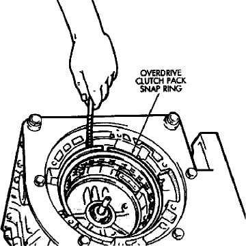
Fig. 42 installing Overdrive Brake Snap Ring
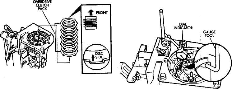
Fig. 41 Install Overdrive Clutch Pack Fig. 43 Positioning Gauge Tool And Dial Indicator
Install extension or adapter housing on trans
mission. Tighten housing/adapter bolts to 34 N«m (25
ft-lbsj torque.
Install speed sensor (Fig. 66). Tighten sensor bolt
to 7.4 ąm (65 in-lbs) torque and connect sensor wire
harness connector.
(91) Install speedometer driven gear (Fig. 67).
Tighten gear attaching bolt to 19 N-m (175 in-lbs)
torque.
(92) Install converter housing (Fig. 68). Tighten 12
mm diameter housing bolts to 57 N-m (42 ft-lbs) torque.
Tighten 10 mm diameter housing bolts to 34 N-m (25
ft-lbs) torque.
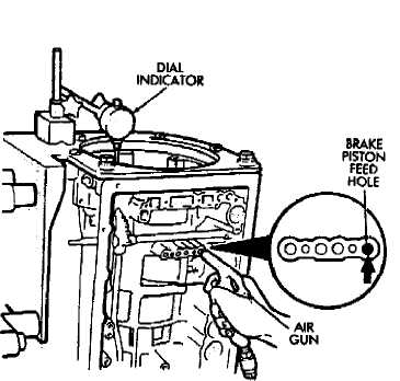
Fig. 44 Checking Overdrive Brake Piston Stroke
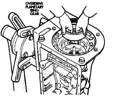
Fig. 46 Installing Overdrive Planetary Ring Gear
Install transmission shift control lever on man
ual valve shaft. Do not install the lever attaching nut
at this time.
Move shift control lever all the way to rear. Then
move it two detent positions forward.
Mount neutral safety switch on manual valve
shaft and tighten switch adjusting bolt just enough to
keep switch from moving (Fig. 69).
Install neutral switch tabbed washer and retain
ing nut (Fig. 69). Tighten nut to 6.9 N«m (61 in-lbs i
torque, but do not bend any of the washer tabs against
the nut at this time.

Fig. 47 Installing Ring Gear Thrust Bearing And Race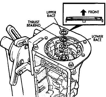
Fig. 45 Installing Overdrive Support Thrust Bearing And Races
Align neutral switch standard line with groove or
flat on manual shaft (Fig. 69).
Tighten neutral switch adjusting bolt to 13 N-m
(9 ft-lbs) torque.
Install shift control lever on manual valve shaft.
Tighten lever attaching nut to 16 ąm(!2 ft-lbs) torque.
Install retaining clamp for wire harness and
throttle cable (Fig, 70).
Install torque converter.
Verify that converter is seated by measuring
distance between converter housing flange and one of
the converter mounting pads (Fig. 71). Use straightedge
and vernier calipers to measure distance. On 4-cyl.
transmissions, distance should be 17.5 mm (.689 in). On
6-cyl. transmissions, distance should be 16.5 mm (.650
in).
Install lower half of transmission fill tube (in
stall upper half after transmission is in vehicle).
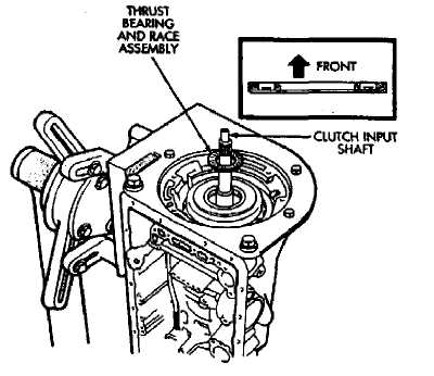
Fig. 50 Installing Input Shaft Thrust Bearing And Race Assembly
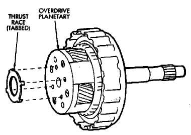
Fig. 48 Installing Planetary thrust Race
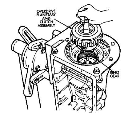
Fig. 49 Installing Overdrive Planetary And Clutch Assembly
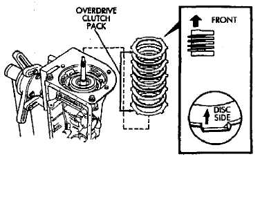
Fig. 51 Installing Overdrive Clutch Pack
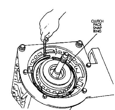
Fig. 52 Installing Clutch Pack Snap Ring
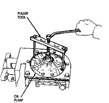
Fig. 54 Installing Oil Pump
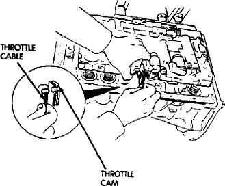
Fig. 55 Installing Throttle Cable
OILF
Fig. 53 Installing Oil Pump Thrust Race

Fig. 57 Installing Accumulator Pistons
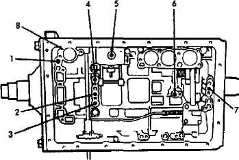
1. OVERDRIVE DIRECT CLUTCH FEED
2. DIRECT CLUTCH FEED
3. FORWARD CLUTCH FEED
4. OVERDRIVE BRAKE FEED
5. SECOND COAST BRAKE FEED
6. SECOND BRAKE FEED
7. FIRST-EEVERSE BRAKE FEED
8. OVERDRIVE CLUTCH ACCUMULATOR PISTON HOLE
Fig. 56 Clutch And Brake Feed Hole Locations
BLOCK THISHOLE WHEN CHECKING DIRECT CLUTCH OPERATION!

Fig. 60 Connecting Throttle Cable
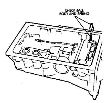
Fig. 58 Installing Cheek Ball Body And Spring
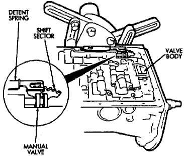
Fig. 59 Aligning Manual Valve, Shift Sector And Detent Spring
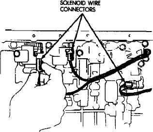
Fig. 61 Connecting Valve Body Solenoid Wires
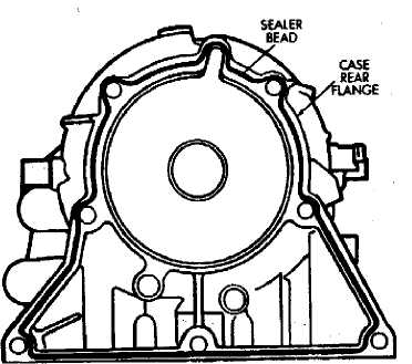
Fig. 65 Applying Sealer To Case Rear Flange
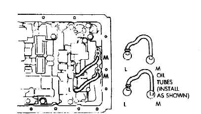
Fig. 62 Installing Valve Body Oil Tubes
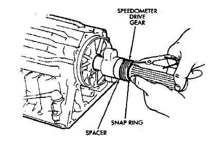
Fig. 64 Installing Spacer And Speedometer Drive Gear
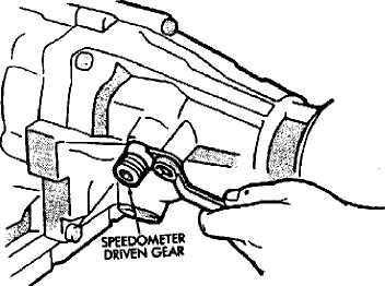
Fg. 67 Installing Speedometer Driven Gear
Fig, 66 Installing Speed Sensor
SPI-ED SENSOR BOTOR
Fig. 63 Installing Speed Sensor Rotor And Key
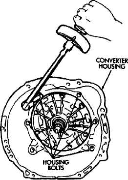
Fig. 68 Installing Converter Housing

Fig. 70 Installing Cable/Harness Clamps
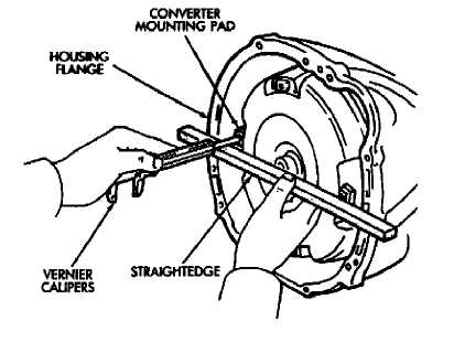
Fig. 71 Checking Converter Installation
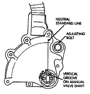
Fig. 69 Neutral Switch Installation/Adjustment