PVC & CRANKCASE VENTILATION SYSTEM
1988 Jeep Cherokee
1987-89 Crankcase Ventilation PCV AND CCV SYSTEMS
Jeep
DESCRIPTION
Crankcase ventilation systems are designed to prevent contaminating hydrocarbons from escaping to the atmosphere. This is accomplished by routing vapors from the crankcase through a vacuum-controlled ventilating valve (PCV Valve) into the intake manifold. In the intake manifold, the crankcase vapors mix with the air/fuel mixture and are burned in the combustion process. PCV systems are used on all 4.2L and 5.9L engines. 2.5L and 4.0L engines do not employ PCV systems, instead they are equipped with a Crankcase Ventilation System (CCV). The CCV system performs the same function as a conventional PCV system, but does not use a vacuum controlled valve.
OPERATION
PCV SYSTEM
Air is supplied to the crankcase ventilation system through a crankcase ventilating filter assembly, located in air cleaner housing or on rocker arm cover.
When engine is operating, fresh air enters crankcase ventilation system through the air cleaner and filter.
Air then flows into the rocker arm cover and valve compartment. It combines with blow-by gas and unburned air/fuel mixture and burns in combustion chamber. See Fig. 1.
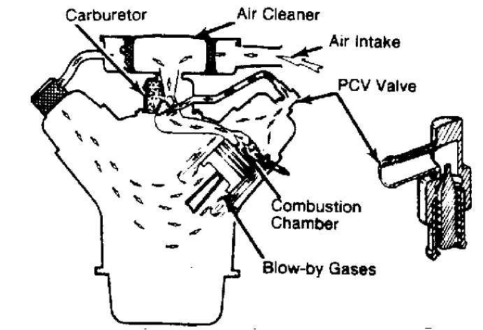
Fig. 1: Typical Crankcase Ventilation System
Ventilator valve is held closed by spring pressure when engine is not running. See Fig. 2. This prevents accumulation of hydrocarbon fumes from collecting in intake manifold, which could
result in hard starting.
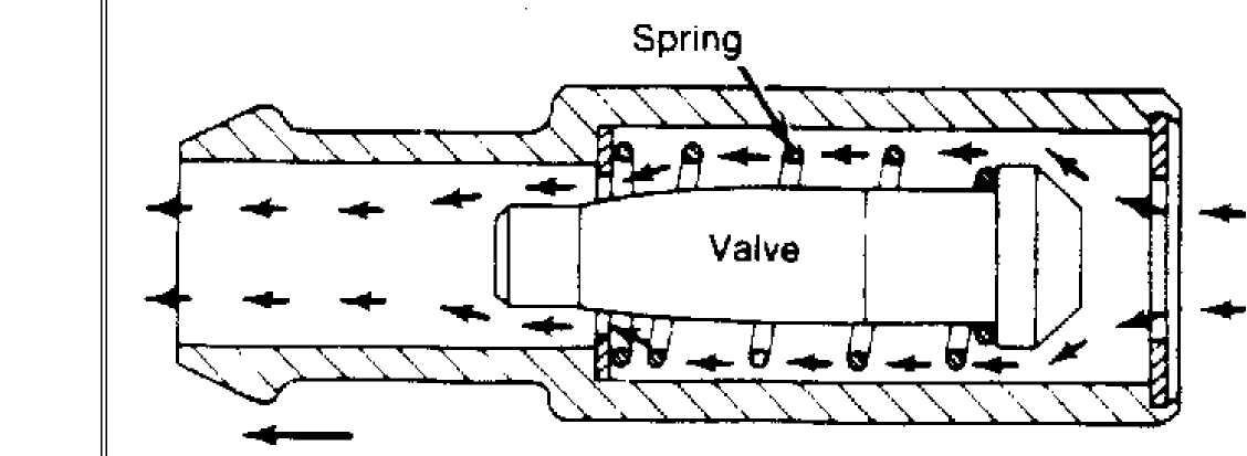 Fig.
2:
Fig.
2:
Ňî Carburetor
Typical PCV Valve & Airflow
When engine is started, manifold vacuum pulls valve open against spring pressure. As long as there is engine vacuum, the valve floats, permitting crankcase fumes to enter intake manifold.
A baffle in rocker arm cover prevents oil from being drawn into intake manifold through ventilator valve.
If the engine backfires, the ventilator valve will close. This will prevent ignition of fumes in crankcase.
During certain engine operations, more blow-by is created than ventilator valve can handle. Excess blow-by is returned to air cleaner and carburetor through rocker arm cover and breather assembly. It is then burned in the combustion chamber.
A breather assembly acts as separator to keep oil from being drawn into air cleaner during this operation.
CCV SYSTEM
As stated above, the CCV system performs the same function as a conventional PCV system, but does not use a vacuum controlled valve.
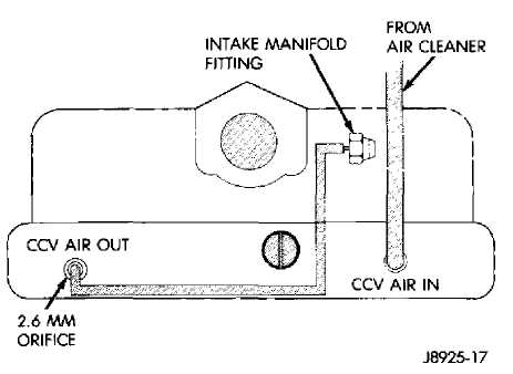
A molded vacuum tube connects manifold vacuum to a grommet on top of the cylinder head cover at the dash panel end. The grommet contains a metered orifice of a calibrated size that meters the amount of crankcase vapors drawn out of the engine. A fresh air supply hose from the air cleaner is also connected to the front of the cylinder head cover on 4.0L engines and to the rear of the cover on 2.5L engines.
When the engine is operating, fresh air enters the engine and mixes with crankcase vapors. Manifold vacuum draws the vapor/air mixture through the metered orifice and into the intake manifold. The vapors are consumed during combustion.
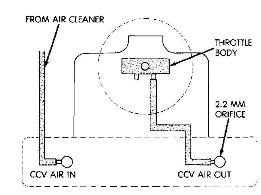
Fig. 3: CCV System 2.5L Engine


 MW 29 159ă
_ I
i ß ^Ě× ...„
. , 1992
MW 29 159ă
_ I
i ß ^Ě× ...„
. , 1992
Fig. 4: CCV System 4.0L Engine
TESTING
To test crankcase ventilation system, start engine and allow it to reach normal operating temperature. Make sure engine is idling at normal curb idle, and perform following checks:
Remove
PCV valve from its mounting. If valve is
functioning properly,
hissing noise will be heard as air passes
through
it. Strong vacuum should be felt when your finger is placed
over
valve inlet.
While
finger is over inlet, check for presence of vacuum
leaks in hose
line and at all connections. Reinstall PCV valve,
remove
crankcase air inlet hose at air cleaner.
Loosely
hold piece of stiff paper over opening at end of
inlet hose.
Paper should be sucked against hose opening with
noticeable force
after sufficient time has elapsed for crankcase
pressure to lower
(usually about a minute). For final check,
stop
engine, remove PCV valve and shake
it. Metallic clicking noise should
be heard, indicating valve is
free.
If system
passes both engine running and stopped tests,
it is functioning
properly. No further tests are required. If it has
failed either
test, replace appropriate components and retest. If it
does not
pass on second try, clean system.
MAINTENANCE
Engine may idle slow or rough due to clogged ventilator valve or system. Therefore, never adjust carburetor idle without first checking valve and system.
If ventilator valve or system becomes clogged, all crankcase ventilation will stop, and serious engine damage could result.
Although following manufacturers’ service procedures give specific intervals, it is recommended the crankcase ventilation system be checked more frequently if vehicle is operated under severe conditions (extreme dust, prolonged idling, trailer hauling or short trips in cold weather).
PCV VALVE
Replace PCV valve every 30,000 miles. Valve is located on rocker arm cover of 4-cylinder, 6-cylinder and V6 models and on intake manifold of V8 models.
FILTER ELEMENT
Clean filter element every 30,000 miles. Filter is located inside air cleaner of 4-cylinder, 6-cylinder and V6 models and in oil filler cap of V8 models.