TRANSFER CASE - COMMAND TRAC DIAGNOSIS
1988 Jeep Cherokee
1984-90 Drive Axles - Transfer Case - Electronic Diagnosis Cherokee, Wagoneer, Wrangler (1987-90)
VACUUM CONTROL SYSTEM
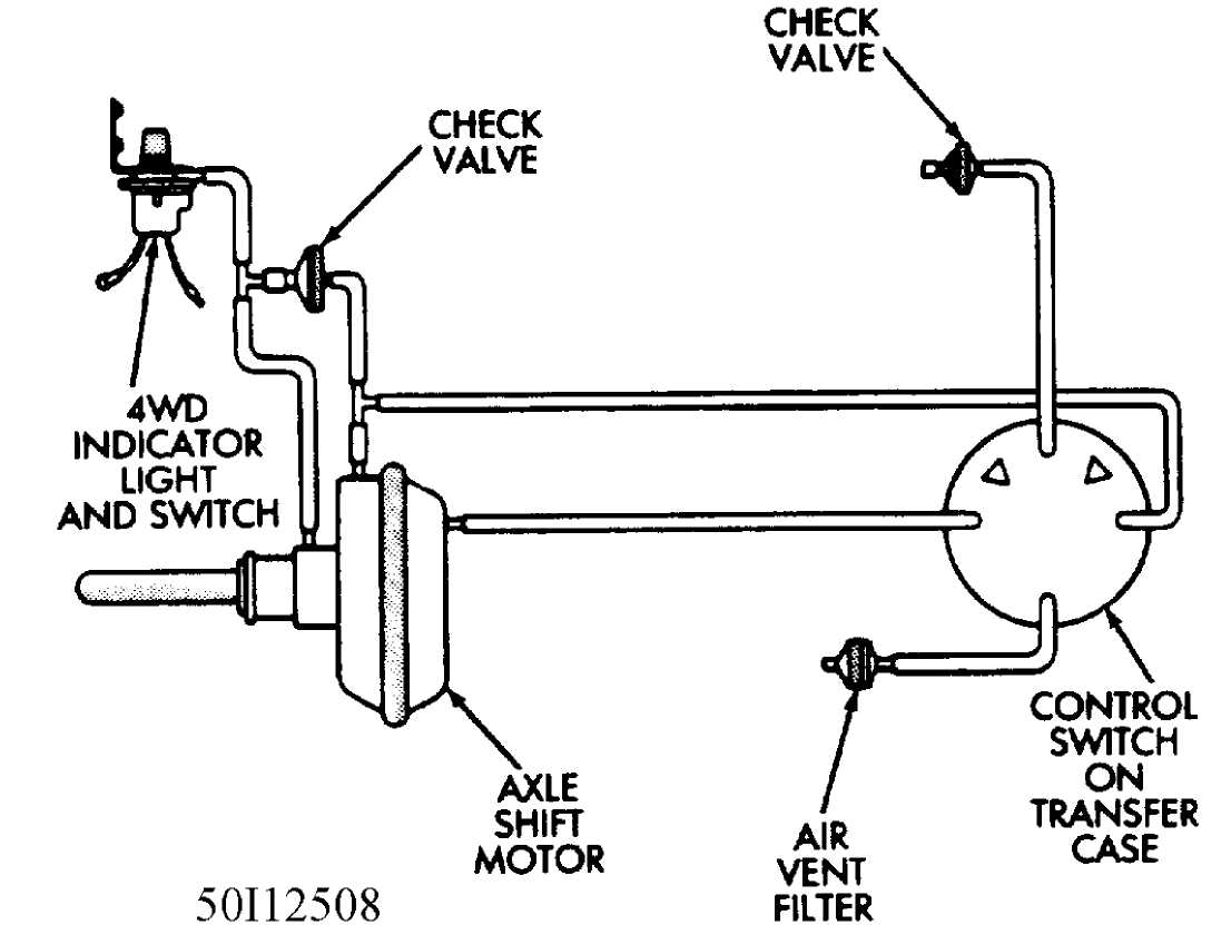
The Command-Trac vacuum switch consists of a vacuum control switch on the transfer case, an air vent filter, a vacuum shift motor (located on front axle), a four-wheel drive indicator light and vacuum switch, two vacuum check valves and an interconnecting vacuum harness. See Fig. 1.

Fig. 1: Command-Trac Vacuum Control System
AXLE SHIFT MOTOR FUNCTIONAL TEST
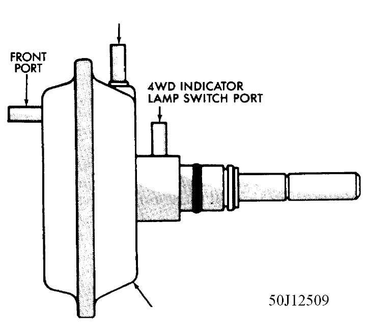
1) Raise vehicle. Disconnect vacuum harness from axle shift motor and connect a vacuum pump to vacuum shift motor port. See Fig. 2.
Apply
15 in. Hg. (51 kPa)
of vacuum to front port and
rotate
right front wheel to fully disengage outer and intermediate
axle
shafts (i.g., into two wheel drive operation).
The
shift motor should maintain vacuum applied to front
port
for a minimum of 30 seconds. If motor does
not maintain vacuum,
replace it. If
motor does maintain vacuum, proceed to next step.
Disconnect
vacuum pump from vacuum shift motor front port.
See
Fig. 2. Connect vacuum pump to vacuum
shift motor rear port, cap
port for
indicator lamp sw., and apply 15 in. Hg
(51 kPa) of vacuum to
rear
port.
The
shift motor should maintain the vacuum applied to rear
port
for a minimum of 30 seconds. If shift
motor does not maintain
vacuum, replace it. If motor does
maintain vacuum, proceed to next
step.
Remove cap
from port for indicator lamp sw. and determine
if vacuum was
present at this port. If vacuum was present, the shift
motor
functions normally. If vacuum was not present, proceed to next
step.
Apply
15 in. Hg. (51 kPa)
of vacuum to shift motor rear
port.
Rotate right front wheel as necessary and ensure that outer
and
intermediate axle shafts are completely engaged. The axles
must be
completely engaged (i.e. into
four-wheel drive operation) to open port
for
indicator lamp switch.
Determine
if vacuum is present at port for indicator lamp
switch again. If
vacuum was present at por, shift motor functions
normally. If
vacuum was not present at port, replace shift motor.

SHIFT MOTOR
Fig. 2: Axle Vacuum Shift Motor
REAR PORT
AXLE SHIFT MOTOR AND HOUSING REMOVAL & INSTALLATION
REMOVAL (60/70 SERIES AND MODEL 81 VEHICLES)
Raise and
support vehicle. Position a drain pan under
shift motor housing.
Disconnect vacuum harness.
Remove
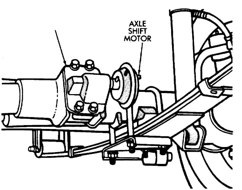
housing attaching bolts. Remove housing, motor and
shift fork as
a unit. See Fig. 3.
Mark shift fork and housing for installation reference.
Rotate
shift motor and remove shift fork and motor
retaining
snap rings.
Remove shift motor from housing.
Remove
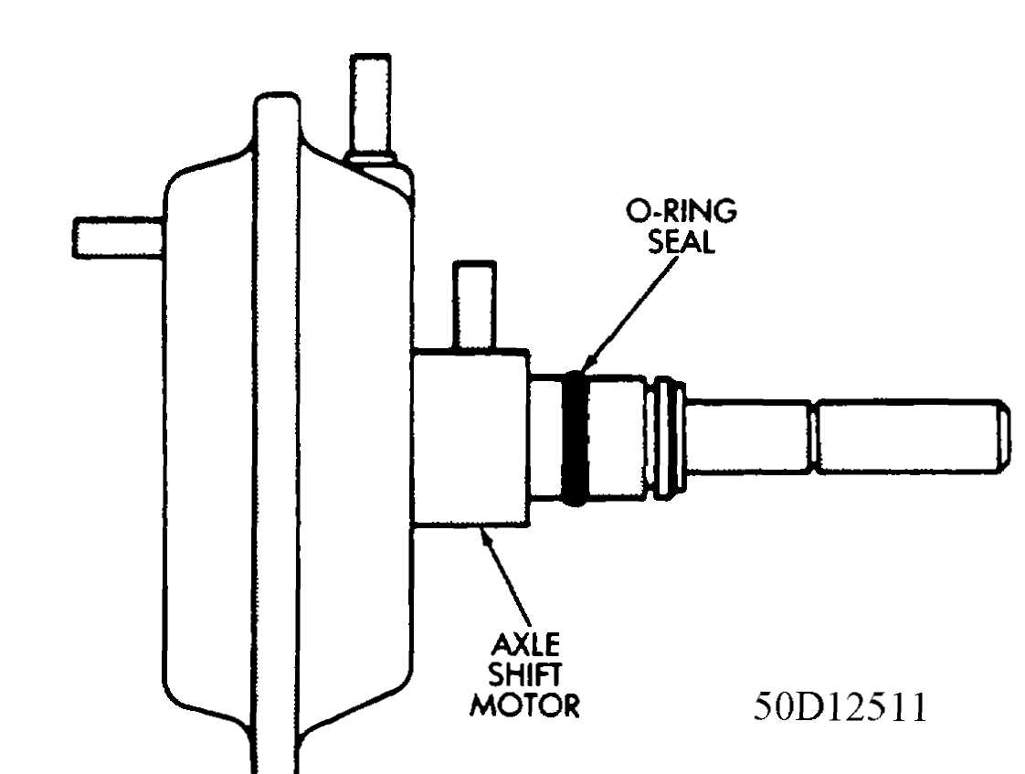
O-ring seal from shift motor shaft. See Fig. 4.
Discard
O-ring seal.
INSTALLATION (60/70 SERIES AND MODEL 81 VEHICLES)
Add
5 ounces (148 ml)
of SAE 75W-90 grade GL 5 gear
lubricant
to axle through shift motor housing opening.
Insatll
a replacement O-ring seal on shift motor shaft.
See
Fig. 4.
Insatll
shift motor in housing with retaining snap rings
and slide shift
fork onto shaft with reference mark aligned.
Engage
shift fork with shift collar and install housing
attaching
bolts. See Fig. 3. Tighten bolts with 101
inch-lbs. (11 N.m)
torque.
Connect vacuum harness to shift motor and lower vehicle.

AXLE
SHIFT
MOTOR
50C12510
Fig. 3: Axle Vacuum Shift Motor and Housing
HOUSING

Fig. 4: Axle Vacuum Shift Motor Shaft O-Ring Seal