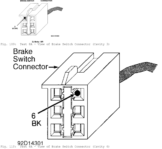
Fig. 109: Test 8A - View of Brake Switch Connector (Cavity 3)
Fig. 110: Test 8A - View of Brake Switch Connector (Cavity 6)
TEST 8B - CODE 706 - BRAKE SWITCH CIRCUIT
NOTE:
Perform TEST 8A - CODE 706 - BRAKE SWITCH CIRCUIT before
proceeding.
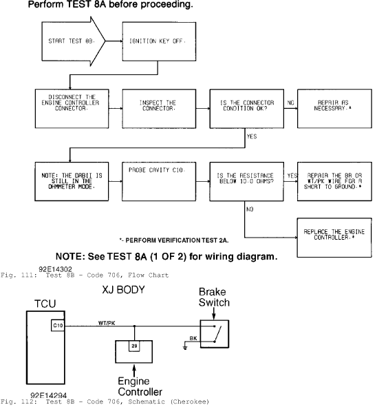
Fig. 111: Test 8B - Code 706, Flow Chart
Fig. 112: Test 8B - Code 706, Schematic (Cherokee)
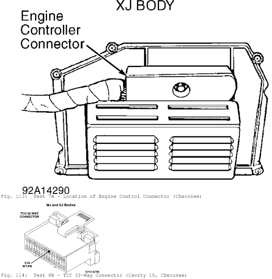
Fig. 113: Test 7A - Location of Engine Control Connector (Cherokee)
Fig. 114: Test 8B - TCU 32-Way Connector (Cavity 10, Cherokee)
TEST 9A - WRONG TCU
NOTE:
Perform TEST 1A - VERIFICATION OF THE COMPLAINT
before proceeding.
NOTE: The AW-4 is used only on 4.0L. In earlier years, it was
used with 2.5.
The DRB-II has determined that the wrong Transmission Control
Unit (TCU) has been installed in the vehicle. There are two
transmission control units available for the Jeep AW4 transmission.
One is for the 4-cylinder 2.5L engine and the other is for the
6
cylinder 4.0L engine.
1) using the DRB-II, read MODULE INFO. See HELP 1 for
assistance.
2) Determine what vehicle should be in the vehicle.
* 2.5L Engine: TCU 02 (Used in earlier years only)
* 4.0L Engine: TCU 01 (1993-94)
3) If the wrong transmission control unit is installed, the
vehicle shift points will be slightly different (the 2.5L engine TCU
has higher shift points)
.
TEST 10A - TESTING FOR INTERMITTENT SPEED SENSOR
NOTE:
Perform TEST 1A - VERIFICATION OF THE COMPLAINT
before proceeding.

Fig. 115: Test 10A - Flow Chart (1 of 2)
Fig. 116: Test 10A - Schematic (Cherokee)
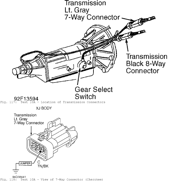
Fig. 117: Test 10A - Location of Transmission Connectors
Fig. 118: Test 10A - View of 7-Way Connector (Cherokee)
NOTE: See Fig. 115 for wiring diagram.

Fig. 119: Test 10A - Flow Chart (2 of 2)
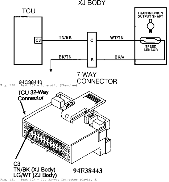
Fig. 120: Test 10A - Schematic (Cherokee)
Fig. 121: Test 10A - TCU 32-Way Connector (Cavity 3)
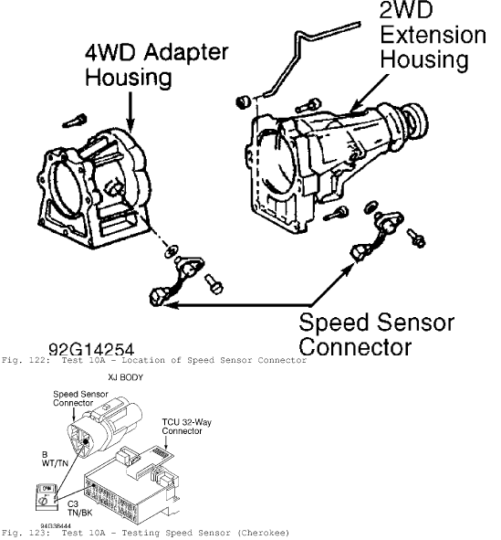
Fig. 122: Test 10A - Location of Speed Sensor Connector
Fig. 123: Test 10A - Testing Speed Sensor (Cherokee)
WIRING DIAGRAMS
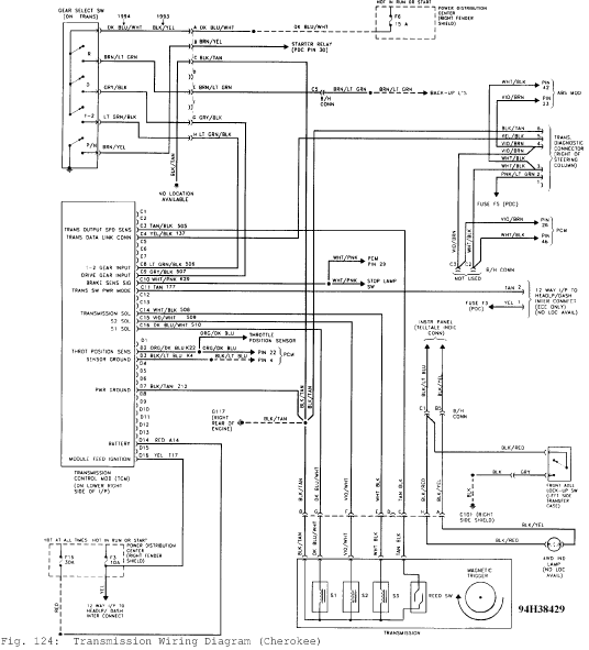
Fig. 124: Transmission Wiring Diagram (Cherokee)

Fig. 125: TCM Connector Terminals I.D., Circuits & Functions
Courtesy of Chrysler Corp.
REMOVAL & INSTALLATION
BRAKE SWITCH
Removal
Remove lower steering column cover or trim panels for access
to brake switch (if necessary). Disconnect brake switch electrical
connector. Thread brake switch from retainer and remove.
Installation
1) Install brake switch in retainer. Reconnect brake switch
electrical connector.
2) To check brake switch adjustment, slightly depress brake
pedal and note operation of brake switch plunger. Brake switch plunger
should fully extend when brake pedal free play is taken up and brake
application begins.
3) Clearance between brake switch plunger and brake pedal
should be approximately 1/8". If clearance is not within
specification, pull brake pedal rearward as far as possible.
4) Brake pedal should contact brake switch plunger, pushing
brake switch backward in retainer to provide proper adjustment. Ensure
brake lights operate.
5) Recheck clearance between brake switch plunger and brake
pedal with brake pedal depressed and free play taken up. Reinstall
lower steering column cover or trim panels.
NEUTRAL SAFETY SWITCH
NOTE:
Neutral safety switch may be referred to as park/neutral or
gear select switch.
Removal
1) Apply parking brake. Raise and support vehicle. Disconnect
electrical connector at neutral safety switch. Pry lock washer tabs
away from retaining nut. See Fig. 126.
2) Remove retaining nut, lock washer and adjusting bolt. See
Fig. 126. Remove neutral safety switch from manual valve shaft.
Installation
1) Disconnect shift control rod from transmission shift
lever. Rotate transmission shift lever fully rearward and then forward
2 detents to Neutral position.
2) Install neutral safety switch on manual valve shaft.
Install adjusting bolt but DO NOT tighten at this time.
3) Install lock washer and retaining nut. Tighten retaining
nut to specification. See TORQUE SPECIFICATIONS. DO NOT bend over lock
washer tabs at this time.
4) Ensure transmission is still in Neutral. Rotate neutral
safety switch and align neutral standard line with vertical groove on
manual valve shaft. See Fig. 126.
5) Tighten the adjusting bolt to specification. Refer to the
TORQUE SPECIFICATIONS table. Bend lock washer tabs over. Reconnect
shift control rod and electrical connector. Ensure vehicle starts in
Park and Neutral only.
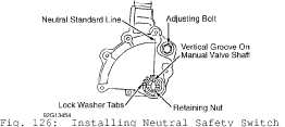
Fig. 126: Installing Neutral Safety Switch
Courtesy of Chrysler Corp.
SPEED SENSOR
Removal & Installation
1) Disconnect electrical connector at speed sensor located on
adapter housing or extension housing. Remove bolt and speed sensor.
Remove "O" ring from speed sensor.
2) To install, reverse removal procedure using NEW "O" ring.
Tighten bolt to specification. See TORQUE SPECIFICATIONS at end of
article.
THROTTLE POSITION SENSOR (TPS)
Removal & Installation
1) Note location of TPS electrical connector. See Fig. 127.
Disconnect electrical connector. Remove screws and TPS.
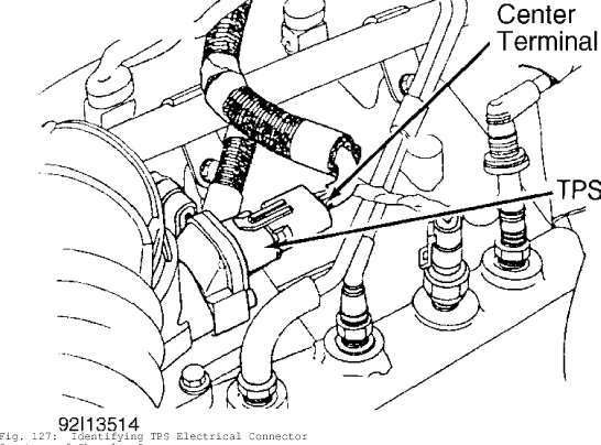
Fig. 127: Identifying TPS Electrical Connector
Courtesy of Chrysler Corp.
2) To install, reverse removal procedure. Ensure throttle
shaft on throttle body engages socket tangs on TPS. See Fig. 128.
Tighten screws. Manually operate throttle and ensure no binding
exists. Reinstall electrical connector.
NOTE: TPS must be installed so it can be rotated a few degrees. If
TPS cannot be rotated, reinstall TPS with end of throttle
shaft on other side of TPS socket tangs.
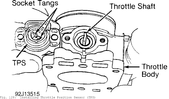
Fig. 128: Installing Throttle Position Sensor (TPS)
Courtesy of Chrysler Corp.
TRANSMISSION CONTROL MODULE (TCM)
Removal & Installation (Cherokee)
Ensure ignition is off. Disconnect electrical connector from
TCM, located behind right side of instrument panel. See Fig. 129.
Remove fastener and TCM from instrument panel. To install, reverse
removal procedure.
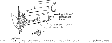
Fig. 129: Transmission Control Module (TCM) I.D. (Cherokee)
Courtesy of Chrysler Corp.
VALVE BODY SOLENOID
Removal
1) Raise and support vehicle. Remove drain plug and drain
transmission fluid. Remove bolts and oil pan. Remove bolts, oil screen
and gasket.
2) Disconnect electrical connectors from valve body solenoid.
Mark electrical connector location for reassembly reference if more
than one valve body solenoid is being removed. Remove bolt, valve body
solenoid and "O" ring.
CAUTION:
DO NOT allow components to fall from valve body when
removing valve body solenoid.
Installation
1) To install, reverse removal procedure using NEW "O" ring
and NEW gaskets. Tighten valve body solenoid bolt and oil screen bolt
to specification. See TORQUE SPECIFICATIONS at end of article.
2) Ensure magnet is installed in oil pan and does not
interfere with valve body oil tubes. Apply 1/8" bead of Loctite 599
sealant on oil pan mounting flange. Install oil pan. Install and
tighten bolts to specification. See TORQUE SPECIFICATIONS.
3) Install NEW gasket and drain plug. Tighten drain plug to
specification. See TORQUE SPECIFICATIONS at end of article. Fill
transmission to proper fluid level with Mopar Dexron-IIE/Mercon ATF.
TORQUE SPECIFICATIONS
TORQUE SPECIFICATIONS