NOMENCLATURE | FUNCTION |
Overdrive Direct Clutch | Connects overdrive sun gear and overdrive carrier |
Overdrive Brake | Prevents overdrive sun gear from turning either clockwise or counterclockwise |
Overdrive One-Way Clutch | When transmission is driven by engine, connects overdrive sun gear and overdrive earner |
Forward Clutch | Connects input shaft and front ring gear |
Direct Clutch | Connects input shaft and front and rear sun gear |
Second Coast Brake | Prevents front and rear sun gear from turning either clockwise or counterclockwise |
Second Broke | Prevents outer race of No. 1 one-way clutch from turning either clockwise or counterclockwise, thus preventing front and rear sun gear from turning counterclockwise |
First/Reverse Brake | Prevents rear planetary carrier from turning either clockwise or counterclockwise |
One-Way Clutch No. 1 | When second brake is operating, prevents front and rear sun gear from turning counterclockwise |
One-Way Clutch No. 2 | Prevents rear planetary carrier from turning counterclockwise |
Fig. 7 Component Function Chart
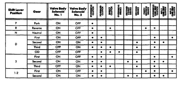
•=Applied
Fig. 8 Component Application Chart
HYDRAULIC SYSTEM
The basic hydraulic system consists of the oil pump, valve body and solenoids and four hydraulic accumulators. The oil pump provides the necessary system lubrication and operating pressure.
The valve body controls application of the clutches, brakes, second coast band and the torque converter lockup clutch. The valve body solenoids control sequencing of the 1-2, 2-3 and 3-4 shift valves within the valve body. The solenoids are activated by signals from the TCU.
The accumulators are used in the clutch and brake feed circuits to control initial apply pressure. Spring loaded accumulator pistons modulate the initial surge of apply pressure for smooth engagement.
Oil Pump
A gear-type oil pump is used in all AW-4 transmissions. The pump gears are mounted in the oil pump body. The drive gear is operated by the torque converter hub. Drive tangs on the hub engage in drive slots in the drive gear.
Valve Body Components
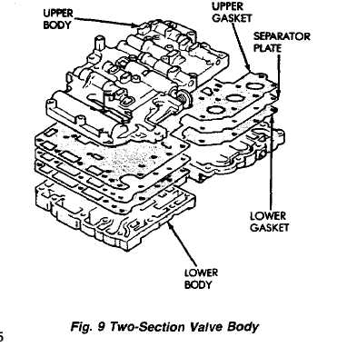
Transmission operating pressure is supplied to the clutch and brake apply circuits through the valve body. The valve body consists of an upper body, lower body, separator plate and upper and lower gaskets (Fig. 9). The various spool valves, sleeves, plugs and springs are located within the two body sections.
The manual valve, 1-2 shift valve, primary regulator valve, accumulator control valve, check balls, solenoids and oil strainers are located in the lower body section (Fig. 10). The remaining control and shift valves plus
check balls and one additional oil strainer are located in the upper body section (Fig. 11).
Manual Valve
The manual valve is operated by the gearshift linkage. The valve diverts fluid to the apply circuits according to shift lever position.
Primary Regulator Valve
The primary regulator valve (Fig. 13) modulates line pressure to the clutches and brakes according to engine load. The valve is actuated by throttle valve pressure.
DIAGNOSIS INFORMATION
GENERAL DIAGNOSIS INFORMATION
The TCU used with the AW-4 transmission has a self-diagnostic program. The program is compatible with the DRB II tester.
The AW-4 is an electronically controlled transmission. Shift points and sequence in the forward gear ranges are controlled by the TCU. Before attempting repair, it will be necessary to determine if a malfunction is electrical or mechanical.
The DRB II tester will identify faults in the electrical control system. The road test, pressure test, stall test and time lag test plus the general diagnosis charts will help locate faults in the mechanical running gear.
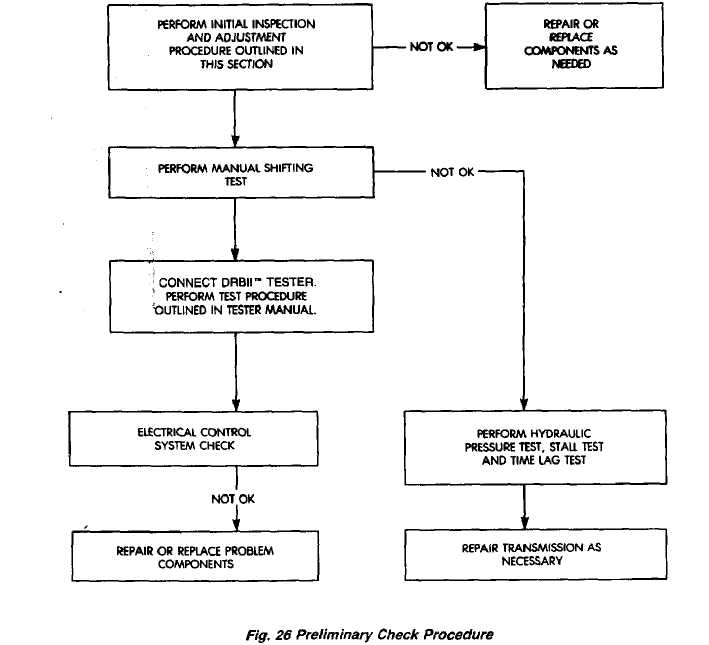
All AW-4 diagnosis should begin with the Preliminary Check Procedure. The procedure is designed to help identify the type of problem (mechanical/electrical) that has occurred. The first step of the procedure is Initial Inspection and Adjustment which is detailed in this section.
INITIAL INSPECTION AND ADJUSTMENT
Check and adjust shift linkage.
Verify line pressure cable operation. Repair or
replace cable if it binds or is damaged.
Check engine throttle operation. Have helper
press accelerator to floor and observe injector throttle
plate movement. Adjust linkage if throttle plate does
not reach wide open position.
Check and adjust line pressure cable if necessary.
Check transmission fluid level when fluid is at
normal operating temperature. Start engine. Shift
transmission through all gear ranges then back to Neu
tral. Correct level is to Full or Add mark on dipstick
with engine at curb idle speed.
Check and adjust neutral switch if necessary.
Check TPS adjustment and operation. Adjust the
sensor if necessary.
MANUAL SHIFTING TEST
This test determines if the problem is related to a
mechanical or electrical component.
Stop engine and disconnect TCU or TCU fuse.
Road test vehicle. Shift transmission into each
gear range. Transmission should operate as follows:
lock in Park
back up in Reverse
not move in Neutral
provide first gear only with shift lever in 1-2 position
operate in third gear only with shift lever in 3 posi
tion
operate in overdrive fourth gear in D position
(4) If transmission operates as described, proceed to
next step. However, if forward gear ranges were diffi
cult to distinguish (all feel the same), or vehicle would
not back up, refer to diagnosis charts. Do not perform
stall or time lag tests.
CAUTION: Do not overspeed the engine during the next test step. Ease off the throttle and allow the vehicle to slow before downshifting.
Continue road test. Manually downshift transmis
sion from D to 3, and from 3 to 1-2 position. Then man
ually upshift transmission through forward ranges
again.
If transmission operation is OK, perform stall,
time lag and pressure tests. If transmission shifting
problem is encountered, refer to diagnosis charts.
If a problem still exists, continue testing with DRB
Ďtester.
HYDRAULIC PRESSURE TEST
Pressure Test Procedure
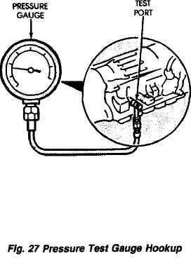
Connect pressure test gauge to test port on pas
senger side of transmission. Use adapter 7554 to con
nect gauge. Be sure test gauge capacity is a minimum
of 300 psi (210OkPa>.
Bring transmission fluid to normal operating tem
perature.
Apply parking brakes and block wheels.
WARNING: DO NOT ALLOW ANYONE TO STAND AT
THE FRONT OR REAR OF THE VEHICLE WHILE PER
FORMING THE FOLLOWING STEPS IN THE PRES
SURE TEST.
Check and adjust engine curb idle speed.
Apply service brakes.
Shift transmission into D range and note line pres
sure with engine at curb idle speed. Pressure should be
53-to-61 psi (363-to-422 kPa).
Press accelerator to wide open throttle position
and note line pressure. Pressure should be 161-to-196
psi (1108-to-1353 kPa).
CAUTION: Do not maintain wide open throttle (or more than three or four seconds at a time.
Shift transmission into Reverse and note line pres
sure with engine at curb idle speed. Pressure should be
-Ţ-87 psi (500-to-598 kPa).
Press accelerator to wide open throttle position
and note line pressure in Reverse. Pressure should be
223-to-273 psi (154O-to-1883 kPa).
CAUTION: Do not maintain wide open throttle for more than three or four seconds at a time.
(10) If line pressure is not within specifications, adjust
line pressure cable arid repeat pressure test.
Pressure Test Analysis
If pressures in D and Reverse are higher than specified, check for the following:
• line pressure cable loose, worn, binding or out of adjustment
• throttle valve, downshift plug, throttle cam sticking,
worn or damaged
• primary regulator valve sticking, worn, or damaged
If pressures in D and Reverse are lower than specified,
check for the following:
line pressure cable loose, worn, binding or out of
adjustment
throttle valve, downshift plug, throttle cam sticking,
worn or damaged
primary regulator valve sticking, worn, or damaged
oil pump gears or housing worn or damaged
overdrive clutch worn or damaged
If pressures are low in D range only, check for the following:
forward clutch worn or damaged
fluid leakage in D range circuit (component seal and
O-rings)
If pressures are low in Reverse only, check for the following:
shift linkage (and manual valve) out of adjustment
fluid leakage in Reverse circuit (component seal and
O-ringa)
direct clutch worn or damaged
first/reverse brake worn or damaged
STALL TEST
The stall test checks holding ability of the trans
mission clutches and brakes and the torque converter
stator clutch.
Bring transmission fluid to normal (hot) operating
temperature.
Connect tachometer to engine. Position tachome
ter so itcan be viewed from drivers seat.
Apply parking brakes and block wheels.
Apply and bold service brakes.
On 4WD models, shift transfer case into two-wheel
high position.
Start engine.
WARNING: DO NOT ALLOW ANYONE TO STAND AT THE FRONT OR REAR OF THE VEHICLE DURING THE TEST.
(8) Shift transmission into D range.
(9) Press accelerator to wide open throttle position
and note maximum engine rpm. Stall speed should be
2100-to-2400 rpm in D range.
CAUTION: Do not maintain wide open throttle tor more than four or five seconds at a time.
Release throttle and shift transmission into Neu
tral. Allow transmission fluid to cool for 15-20 seconds.
Shift transmission into Reverse.
Press accelerator down to wide open throttle po
sition and note maximum engine rpm. Stall speed
should be 2100-to-2400 rpm in Reverse.
Stall Speed Test Analysis
If engine rpm is lower than specified in D and Reverse, check for the following:
engine output/performance insufficient
stator clutch in torque converter not holding if engine
speed was 1500 rpm or less.
If stall speed in D range is higher than specified, check for the following:
line pressure low
forward clutch slipping
No. 2 one-way clutch not holding
overdrive one-way clutch not holding
If stall speed in Reverse was higher than specified, check for the following:
line pressure low
direct clutch slipping
first/ reverse brake slipping
overdrive one-way clutch not holding
If stall speeds were higher than specified in both D and Reverse, check for the following:
low fluid level
line pressure low
overdrive one-way clutch not holding
TIME LAG TEST
This test checks general condition of the overdrive clutch, forward clutch, rear clutch and first/reverse brake. Condition is indicated by the amount of time required for clutch/brake engagement with the engine at curb idle speed. Engagement time is measured for D and Reverse positions. A stop watch is recommended for test accuracy.
Test Procedure
Check and adjust transmission fluid level if nec
essary.
Bring transmission to normal (hot) operating tem-
pertue.
Apply parking brakes.
Turn off air conditioning unit.
On 4WD models, shift transfer case into two-wheel
high.
Start engine and check curb idle speed. Adjust
speed if necessary. Curb idle must be correct to ensure
accurate test results.
Shift transmission into Neutral and set stop
watch.
During following test steps, start stop watch as
soon as shift lever reaches D and Reverse detents.
Shift transmission into D range and record time it
takes for engagement. Repeat test two more times.
Reset stop watch and shift transmission back to
Neutral.
Shift transmission into Reverse and record time
it takes for engagement. Repeat test two more times.
(12) Engagement time in D range should be a maximum of 1.2 seconds. Engagement time for Reverse should be a maximum of 1.5 seconds.
Time Lag Test Analysis
If engagement time is longer than specified for D range, check for the following:
shift linkage misadjusted
line pressure low
forward clutch worn
overdrive clutch worn or damaged
If engagement time is longer than specified for Re verse, check for the following:
shift linkage misadjusted
line pressure low
direct clutch worn
first/reverse brake worn
overdrive clutch worn or damaged