Remount forward clutch drum on overdrive sup
port (Fig. 6).
Apply compressed air through feed hole in sup
port to remove piston (Fig. 6). Use only enough air
pressure to ease piston out of drum.
Remove and discard clutch piston O-rings.
Remove clutch drum O-ring from rear hub (16) of
the drum.
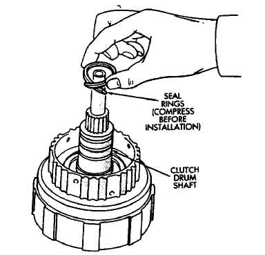
Remove three seal rings from clutch drum shaft
(Fig. 8).
Remove thrust bearing and race assembly from
clutch drum (Fig. 9).
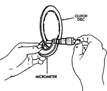
Measure clutch disc thickness (Fig. 10). Mini
mum allowable thickness is: 1.84 mm (.0724 in) on
4-cyl. transmissions and 1.51 mm (.0595 in) on 6-cyl.
transmissions.
Measure free length of piston return springs with
springs mounted in retainer (Fig. 11). Length should be
19.47 mm (.767 in). Replace springs and retainer if
length is incorrect.
Inspect clutch piston check ball (Fig. 12). Ball
should move freely within piston. Check ball seating by
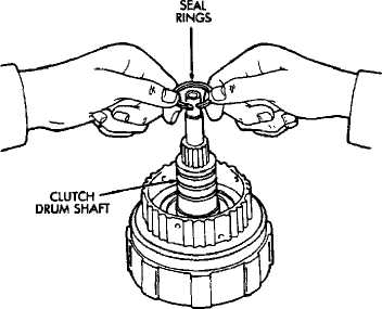
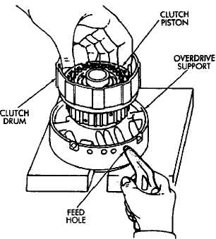
Fig. 8 Removing Clutch Drum Seal Rings
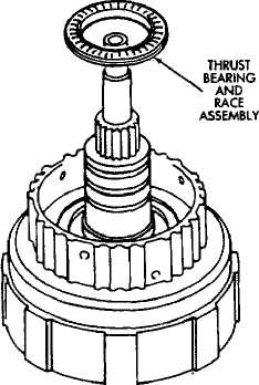
Fig. 7 Removing/Installing Clutch Drum O-Ring
Fig. 9 Removing Clutch Drum Thrust Bearing Assembly
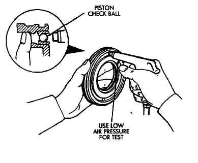
applying low pressure compressed air to ball feed hole. Ball should seat firmly and not leak air.
(21) Measure inside diameter of bushing in clutch drum hub. Maximum allowable diameter is 24.08 mm (.9480 in). Replace clutch drum if bushing inside diameter is greater than specified.
Forward Clutch Assembly
(1) Lubricate bearing and race assembly with petroleum jelly and install it in clutch drum (Fig. 13). Race side of assembly faces downward and toward drum. Bearing rollers face up (Fig. 13)
Coat new clutch drum shaft seal rings with pe
troleum jelly.Before installing drum shaft seal rings,
squeeze (contract) each ring so ring ends overlap (Fig.
14). This tightens ring making clutch installation eas
ier.
Install seal rings on shaft. Keep rings closed as
tightly as possible during installation. Avoid over
spreading them.
Mount clutch drum on overdrive support.
Lubricate and install new O-ring on clutch drum
hub (Fig. 7).
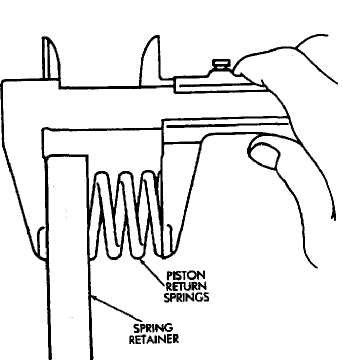
Fig. 10 Measuring Clutch Disc Thickness
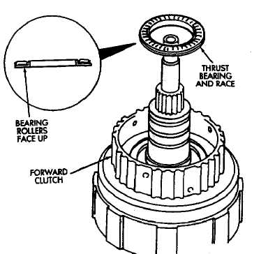
Fig. 11 Checking Return Spring Length 62 Fig- 13 Installing Thrust Bearing And Race
Lubricate and install new O-rings on clutch piston
and install piston in drum.
Install piston return springs.
Compress piston return springs with tool B.Vi.
FM-27 and shop press and install piston snap ring. Be
sure snap ring end gap is not aligned with any notches
in drum.
Install cushion plate in drum. Concave side of plate
faces downward (Fig. 5).
Fig. 14 Installing Clutch Drum Shaft Seal Rings
Install clutch discs, plates and retainer (Fig. 15).
Install tabbed plate followed by disc until required
number of plates and discs are installed. Use six plates
and discs in a 6-cyl. transmission and five plates
and discs in a 4-cyl. transmission.
Install clutch pack snap ring.
Recheck clutch piston stroke length using same
method outlined at beginning of disassembly procedure.
If stroke length is not within specified limits, replace
clutch discs.
Lubricate race and bearing with petroleum jelly
and install them in clutch drum (Fig. 16). Be sure bear-
ng rollers face up and race lip seats in drum as shown.
Verify bearing and race size. Outer diameter of
bearing is 46.7 mm (1.839 in). Outer diameter of race is
48.9 mm (1.925 in). Inner diameter of bearing and race
is 26.0 mm (1.024 in).
Mount forward clutch on direct clutch and check
assembled height (Fig. 17). Height should be 70.3 to
71.5 mm (2.767 to 2.815 in).
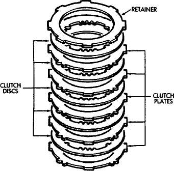
Fig. IS Installing Forward Clutch Discs And Plates
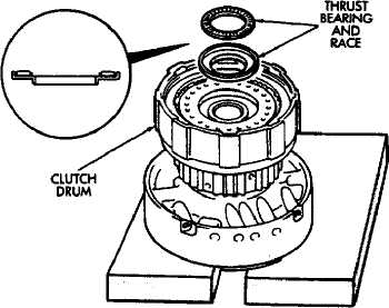
Fig. 16 Installing Thrust Bearing And Pace
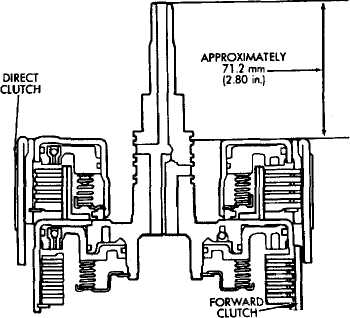
Fig. 17 Checking Forward Clutch Assembled Height
FRONT PLANETARY GEAR OVERHAUL
Front Planetary Disassembly
Remove ring gear from planetary gear (Fig. 1).
Remove front bearing and the two races from ring
gear (Fig. 1).
Remove tabbed thrust race from planetary gear
(Fig. 1).
Remove snap ring attaching planetary gear to
shaft and remove gear.
Remove rear bearing and race from planetary
gear.
Measure inside diameter of ring gear bushing.
Maximum allowable diameter is 24.08 mm (.9480 in). Replace ring gear if bushing inside diameter is greater than specified.
Front Planetary Assembly
Lubricate planetary and ring gear bearings and
races with petroleum jelly.
Identify planetary bearings and races before in
stallation. (Fig. 1). Bearings and races can be identified
by following dimensions:
• Outer diameter of rear bearing is 47.7 mm (1.878 in); inner diameter is 35.5 mm (1.398).
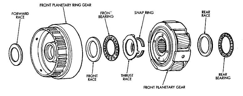
Fig. 1 Front Planetary Gear Components
Outer diameter of rear race 47.6 mm (1.874 in); inner
diameter is 33.7 mm (1.327 in).
Outer diameter of front race is 53.6 mm (2.110 in);
inner diameter is 30.5 mm (1.201 in).
Outer diameter of front bearing is 47.7 mm (1.878 in);
inner diameter is 32.6 (1.283 in).
Outer diameter of forward race is 47.0 mm (1.850 in);
inner diameter is 26.5 mm 1.043 in).
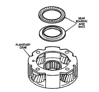
Install rear race and bearing in gear (Fig. 2).
Turn planetary over and install race thrust race
(Fig. 3).
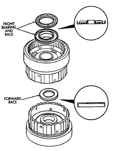
Install front race and bearing and forward race in
ring gear (Fig. 4).
Set planetary gear assembly aside for final as
sembly.
Fig. 2 Installing Front Planetary Rear Bearing and Race
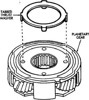
Fig. 3 Installing Front Planetary Thrust Race
Fig. 4 Installing Front Planetary Front Bearing And Races ’
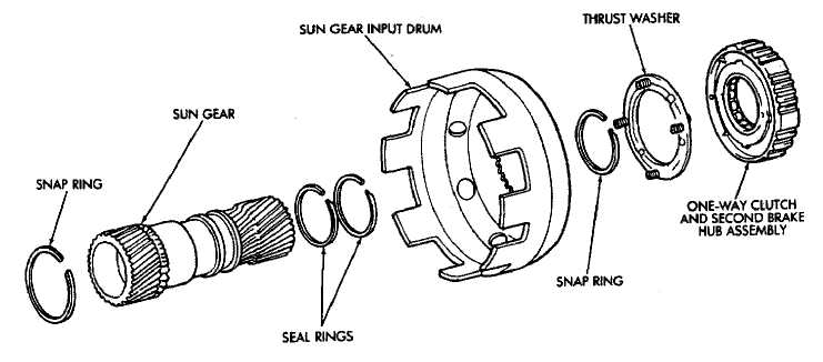
SUN GEAR AND NO. 1 ONE-WAY CLUTCH OVERHAUL
Sun Gear-Clutch Disassembly
Hold sun gear and turn second brake hub clock
wise and counterclockwise (Fig. 2). Hub should rotate
freely clockwise, but lock when turned counterclock
wise. Replace one-way clutch and hub if it does not
operate properly.
Remove one-way clutch/second brake hub assem
bly from drum (Fig. 3).
Remove thrust washer from drum (Fig. 4).
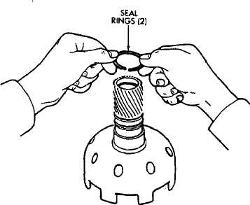
Remove two seal rings from sun gear (Fig. 5).
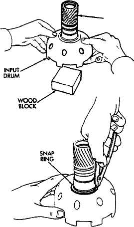
Support sun gear on wood block (Fig. 6). Then
remove first sun gear snap ring and separate drum from
gear.
Remove remaining snap ring from sun gear (Fig.
7).
Measure inside diameter of sun gear bushings
with bore gauge or inside micrometer (Fig. 8). Maxi
mum allowable diameter is 27.08 mm (1.0661 in). Re
place sun gear if bushing inside diameter is greater
than specified.
Sun Gear-Clutch Assembly
(1) Install first snap ring on sun gear.
Fig. 1 Sun Gear And One-Way Clutch Components
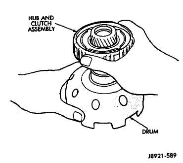
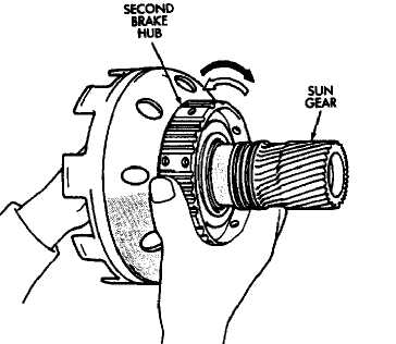
Fig. 3 Removing/Installing Brake Hub And Clutch Assembly
Fig. 2 Checking One-Way Clutch Operation
I
(2) Install sun gear in drum and install remaining snap ring.
C3) Coat replacement seal rings with petroleum jelly and install them on sun gear. Be sure seal ring ends are interlocked.
Install thrust washer. Be sure washer tabs are
seated in drum slots.
Install one-way clutch/second brake hub assembly
on sun gear. Deep side of hub flange faces upward (Fig
9).
Check one-way clutch operation again (Fig. 2).
Hold sun gear and turn second brake hub clockwise and
counterclockwise. Hub should turn clockwise freely, but
lock when turned counterclockwise.
Set sun gear/clutch assembly aside for final as
sembly.
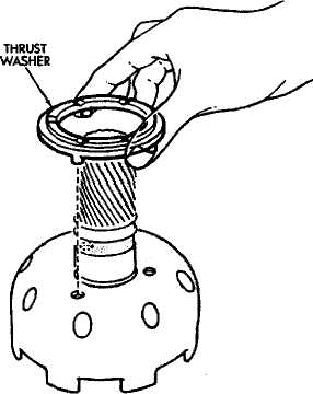
Fig. 4 Removing/Installing Thrust Washer
SUN GEAR
Fig. 6 Removing/Installing Sun Gear
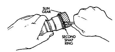
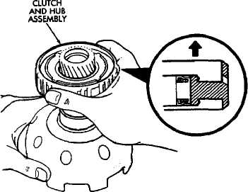
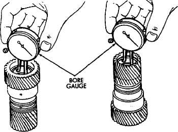
Fig. 7 Removing/Installing Second Snap Ring
Fig. 9 Installing Clutch And Hub Assembly
Fig. 8 Checking Sun Gear Bushings
SECOND BRAKE OVERHAUL
Brake Disassembly
Remove second brake drum from output shaft (Fig.
2).
Set output shaft assembly aside for overhaul. Refer
to Rear Planetary Gear and Output Shaft Overhaul
procedures.
Remove thrust washer from second brake drum
(Fig. 3).
Compress piston return springs with tool B.Vi.
FM-27 and shop press. Then remove piston snap ring
(Fig. 4).
Remove compressor tool and remove spring re
tainer and return springs.
Remove second brake piston and sleeve from drum
with compressed air (Fig. 5). Use only enough air pres
sure to ease piston out of drum.
Remove and discard brake piston O-rings.
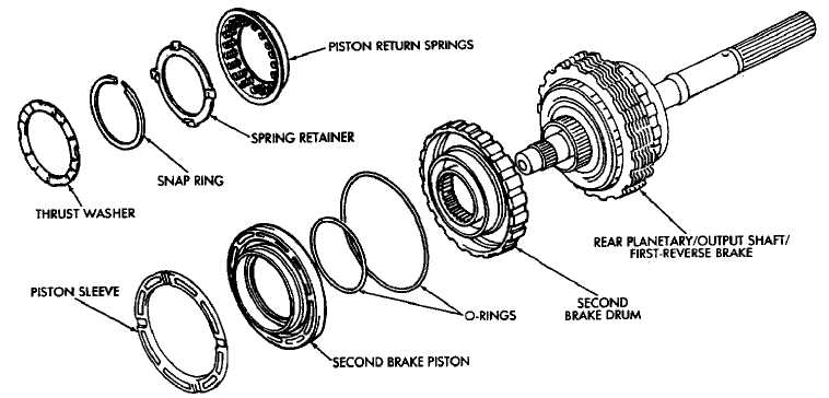
Fig. 1 Second Brake Components
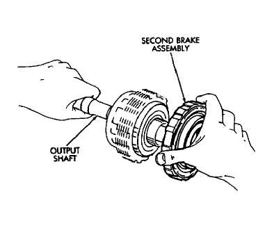

Fig. 2 Removing/Installing Second Brake Assembly
Fig. 3 Removing/Installing Drum Thrust Washer
(4) Check brake piston operation with low pressure compressed air (Fig. 7). Apply air pressure through feed hole in drum. Piston should move smoothly when ap-plying-releasing air pressure.
(8) Measure free length of piston return springs with (4) Check brake piston operation with low pressure
springs mounted in retainer (Fig. 6). Length should be compressed air (Fig. 7). Apply air pressure through feed
16 05 mm (.632 in). Replace return springs if length is hole in drum. Piston should move smoothly when ap-
less than specified. plying-releasmg a.r pressure.
Second Brake Assembly
Lubricate and install new O-rings on brake piston.
Then install brake piston in drum.
Install return springs and retainer on brake pis
ton.
Compress return springs with tool B.Vi. FM-27
and install piston snap ring.
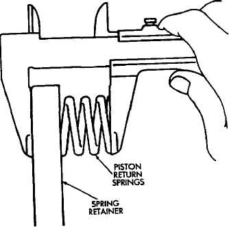

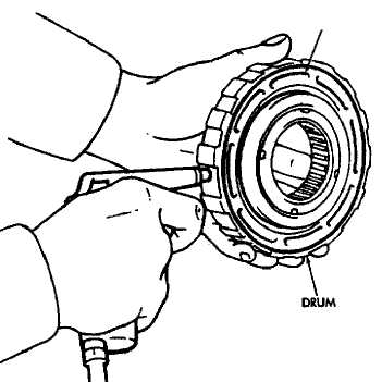
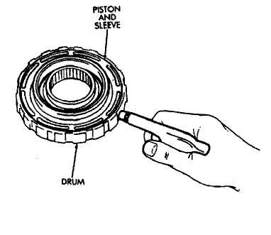
Fig. 4 Removing/Installing Piston Snap Ring
Ďä. á Measuring Piston Return Springs
ąTON
Fig. 5 Removing/Installing Piston And Sleeve
Fig. 7 Checking Piston Operation
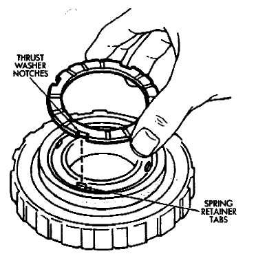
Coat thrust washer with petroleum jelly and in
stall it in drum. Be sure washer notches are aligned
with tabs on spring retainer (Fig. 8).
Set brake components aside for final assembly.
Fig. 8 Installing Thrust Washer
REAR PLANETARY, NO. 2 ONE-WAY CLUTCH AND OUTPUT SHAFT OVERHAUL
REAR PLANETARY GEAR
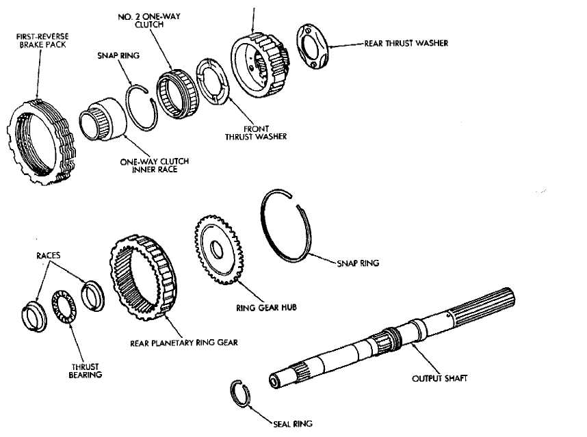
Fig, 1 Rear Planetary, Brake Peck, Clutch And Output Shaft Components
Planetary-Brake Pack-Shaft Disassembly
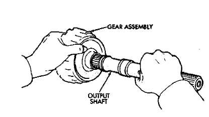
Remove output shaft from gear assembly (Fig. 2).
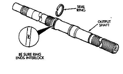
Remove and discard shaft seal ring (Fig. 4).
Remove brake pack from planetary gear (Fig. 4).
Measure thickness of each brake pack disc. Min
imum thickness is 1.51 mm (.0594 in). Replace all discs
if any disc is thinner than specified.
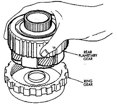
Remove planetary gear from ring gear (Fig. 5).
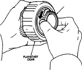
Check No. 2 one-way clutch. Hold planetary gear
and turn clutch inner race in both directions Race
should turn freely counterclockwise, but lock when
turned clockwise. Replace one-way clutch if necessary.
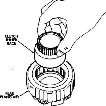
Remove clutch inner race from planetary gear
(Fig. 7).
Remove clutch snap ring and remove No. 2 one
way clutch from planetary (Fig. 8).
Remove front and rear thrust washers from plan
etary gear (Fig. 9).
Fig. 2 Removing/Installing Output Shaft
Remove thrust bearing and washers from ring
gear (Fig. 10).
Remove ring gear snap ring and remove ring gear
hub (Fig. 11).
Inspect and replace any worn or damaged plan
etary gear components.
Assembling Rear Planetary, Brake Pack, Clutch And Shaft
Install hub and snap ring in ring gear (Fig. 11)
Identify ring gear thrust bearing and races races
by following dimensions:
Outer diameter of bottom race (Fig. 10) is 44.8 mm
(1.764 in); inner diameter is 27.6 mm (1.087 in).
Outer diameter of bearing (Fig. 10) is 44.7 mm (1.760
in); inner diameter is 30.1 mm (1.185 in).
Outer diameter of upper race Fig. 10) is 44.8 mm
(1.764 in); inner diameter is 28.8 mm (1.134 in).
Fig. 4 Removing/Installing First-Reverse Brake Pack
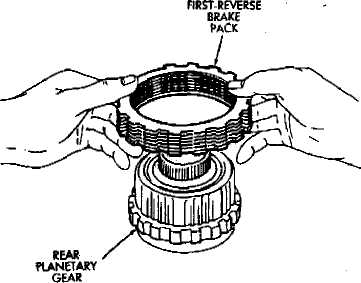
Fig. 3 Removing/Installing Shaft Seal Ring
Fig. Â Removing/Installing Rear Planetary
Coat planetary thrust washers with petroleum
jelly and install them in gear (Fig, 9).
Install No. 2 one-way clutch in planetary gear. Be
sure flanged side of clutch faces upward (Fig. 12).
CLUTCH INNER RACE
(6) Install clutch retaining snap ring and install
clutch inner race (Fig. 7). Turn race counterclockwise to
ease installation.
Fig. 6 Checking No. 2 One-way Clutch Operation
Verify one-way clutch operation. Hold gear and
turn inner race in both directions. Race should turn
freely counterclockwise, but lock when turned clock
wise.
Install planetary gear in ring gear.
Assemble clutch discs and clutch plates (Fig. 4>-
Sequence is disc first, then a plate. Use seven discs
and plates in a 6-cyl. transmission and six discs
and plates in a 4-cyl. transmission.
Install brake pack on planetary gear (Fig, 4).
Install new seal ring on output shaft (Fig. 3). Be
sure ring ends are interlocked as shown.
Set assembled components aside for final assem
bly.
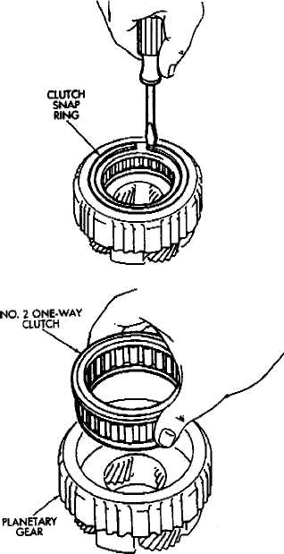
Fig. 7 Removing/Installing Clutch Inner Race
Fig. Â RemovlngJnstellmg One-Way Clutch
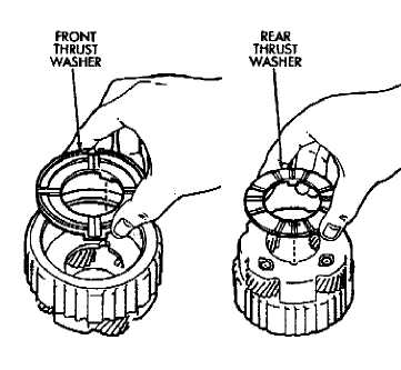
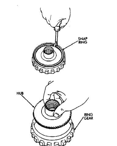
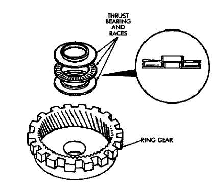
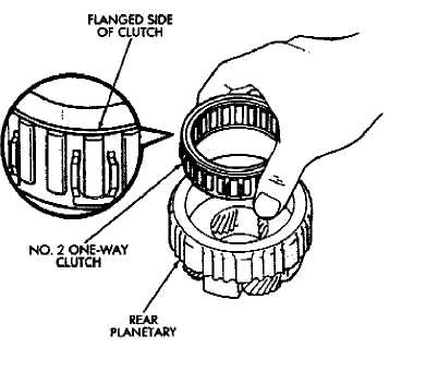
Fig. 9 Removing/Installing Rear Planetary Thrust Washers
Fig. 10 Removing/Installing Ring Gear Thrust Bearing And Races
Fig. 11 Removing/installing Ring Gear Hub
Fig. 12 Installing No. 2 One-Way Clutch
FIRST-REVERSE BRAKE PISTON AND TRANSMISSION CASE OVERHAUL
Brake Disassembly-Inspection
Remove bearing and race assembly from trans
mission case (Fig. 2).
Check first/reverse brake piston operation with
compressed air (Fig. 3). Piston should move smoothly
and not bind or stick- If piston operation is incorrect,
case or piston may require replacement.
Compress piston return springs with tool B.Vi.
FM-28 and remove piston snap ring (Fig. 4).
Remove tool B.Vi. FM-28 and remove piston re
turn springs.
Remove No. 2 first-reverse brake piston with com
pressed air. Apply air through same transmission feed
hole used for checking piston operation.
Remove reaction sleeve with tool B.Vi. FM-31 (Pig.
5). Insert tool flanges under sleeve and lift tool and
sleeve out of case.
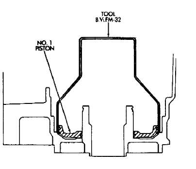
Remove No. 1 first/reverse brake piston with tool
B.Vi. FM- 32 (Fig. 6). Slip tool under piston and lift tool
and piston out of case.
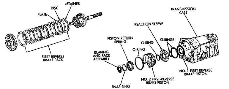
Fig. 1 First-Reverse Brake Pistons And Transmission Case
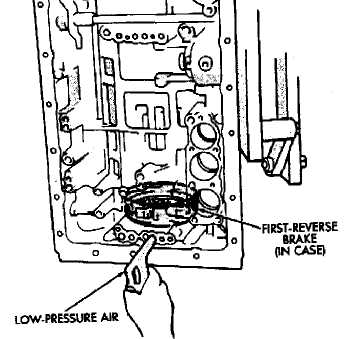
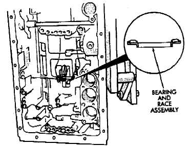
Fig. 2 Removingflnstalling Bearing And Race Assembly
Fig. 3 Checking First-Reverse Brake Piston Operation
 Measure free length of piston return springs with
springs mounted in retainer. Length should be 18.332
mm (.724 in) Replace springs if length is less than this.
Clean transmission case thoroughly with solvent
and dry it with compressed air. Blow compressed air
through oil feed passages to remove solvent residue and
ensure that passages are clear. Inspect the case for wear
or damage. Replace case if necessary.
Assembling First/Reverse Brake Piston
Lubricate and install new O-rings on No. 1 firsts
reverse brake piston and on reaction sleeve (Fig. 7).
Then install piston in sleeve.
Lubricate and install new O-ring on No. 2 brake
piston.
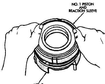
(31 Install assembled No. 1 piston and reaction sleeve on No. 2 piston (Fig. 8).
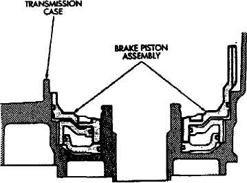
Lubricate and install piston assembly in case (Fig.
9). Align piston and case slots and press piston assembly
into case with hand pressure.
Position piston return springs on No. 2 piston.
Compress piston return springs with tool B.Vi.
FM-28 and install piston snap ring. Be sure snap ring
end gap is not aligned with any tangs on return spring
retainer.
(7) Verify piston operation with compressed air as
outlined in disassembly procedure.
Fig. 4 Removing/Installing Piston Snap Ring
Fig. 6 Removing/Installing First- Reverse Brake No.1 Piston
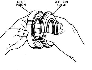
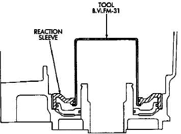
Fig. S Removing/Installing Reaction Sleeve
Fig. 7 Assembling Ho. 1 Piston And Sleeve
(8) Coat bearing and race assembly with petroleum jelly and install it in piston assembly (Fig. 2). Bearing
and race assembly outer diameter is 57.7 mm (2.272 in); inner diameter is 39.2 mm (1.543 in).
Fig, 8 Assembling First-Reverse Brake Pistons
Fig. 9 Installing First-Reverse Brake Piaton Assembly
VALVE BODY OVERHAUL
The valve body assembly consists of two sections which are the upper body and lower body (Figures 1 and
2). Disassembly, inspection and overhaul procedures for each section are outlined separately. Refer to the appropriate procedure as needed.
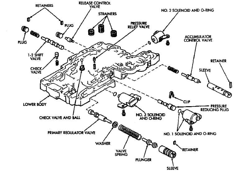
Fig, 1 Lower Body Components (Valve Body)
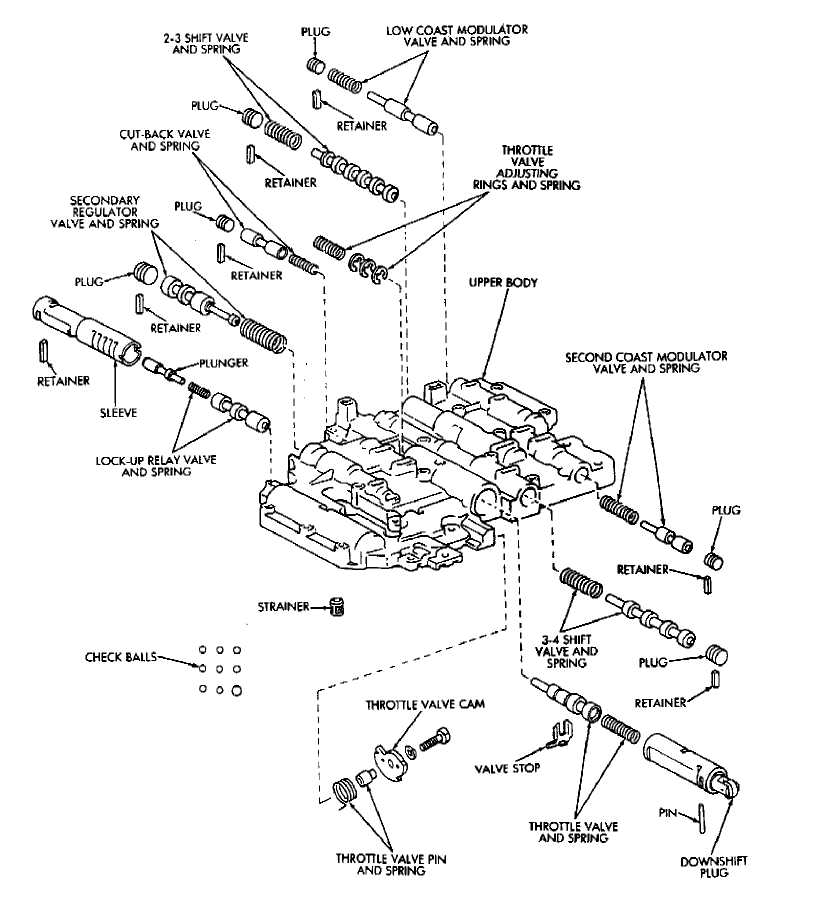
Fig. 2 Upper Body Components (Valve Body)