A/C SYSTEM GENERAL SERVICING
1993 Jeep Cherokee
1993 GENERAL SERVICING General Servicing Procedures
Jeep
USING R-12 & R-134a REFRIGERANT
HANDLING/SAFETY PRECAUTIONS
1) Always
work in a well-ventilated, clean area. Refrigerant
(R-12 or
R-134a) is colorless and invisible as a gas. Refrigerant is
heavier than oxygen and will displace oxygen in a confined area. Avoid breathing refrigerant vapors. Exposure may irritate eyes, nose and throat.
The
system’s high pressure can cause severe injury to eyes
and skin
if a hose were to burst. Always wear eye protection when
working
around A/C system and refrigerant. If necessary, wear rubber
gloves
or other protective clothing.
Refrigerant
evaporates quickly when exposed to atmosphere,
freezing
anything it contacts. If liquid refrigerant contacts eyes or
skin
(frostbite), DO NOT rub eyes or skin. Immediately flush
affected
area with cool water for 15
minutes and consult a doctor or hospital.
Never
use R-134a in combination with compressed air for
leak
testing. Pressurized R-134a in the presence of oxygen
(air
concentrations greater than 60 percent
by volume) may form a
combustible mixture. DO NOT introduce
compressed air into R-134a
containers (full or empty), A/C
system components, or service
equipment.
DO
NOT expose A/C system components to high temperatures
(steam
cleaning for example) as excessive heat will
cause
refrigerant/system pressure to
increase. Never expose refrigerant
directly to open flame. If
refrigerant needs to be warmed, place
bottom
of refrigerant tank in warm water. Water temperature MUST NOT
exceed
125F (52C).
Use
care when handling refrigerant containers. DO NOT
drop,
strike, puncture, or incinerate containers. Use Department
Of
Transportation (DOT) approved (DOT
4BW or DOT 4BA) refrigerant
containers.
Never
overfill refrigerant containers. The safe filling
level
of a refrigerant container MUST NOT exceed 60% of
the
container’s gross weight rating.
Store refrigerant containers below
125F (52C).
Freon
(R-12) will be sold and stored in White colored
containers,
while R-134a refrigerant will be sold and stored in 30 or
50
pound Light Blue containers.
Refrigerant
R-12 and R-134a must never be mixed, as they
and their desiccants
and lubricants are not compatible. If the
refrigerants are mixed,
system cross-contamination or A/C system
component failure may
occur. Always use separate servicing and
refrigerant
recovery/recycling equipment.
10) Read
and follow equipment manufacturer’s instructions for
all
service equipment to be used. The Material Safety Data Sheet
(MSDS),
provided by refrigerant manufacturer/suppliers,
contains
valuable information regarding the safe handling of R-12 or R-134a refrigerants.
CAUTION: Keep work areas ventilated, and avoid operating engines near work area.
IDENTIFYING R-134a SYSTEMS & COMPONENTS
To prevent refrigerant cross-contamination, use following methods to identify R-134a based systems and components.
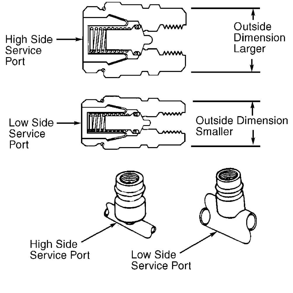
Fittings & "O" Rings
All R-134a based A/C systems use 1/2" - 16 ACME threaded fittings (identifiable by square threads) and quick-connect service couplings. See Fig. 1.
93128488
Fig. 1: Identifying R-134a Service Couplings Courtesy of Chrysler Corp.
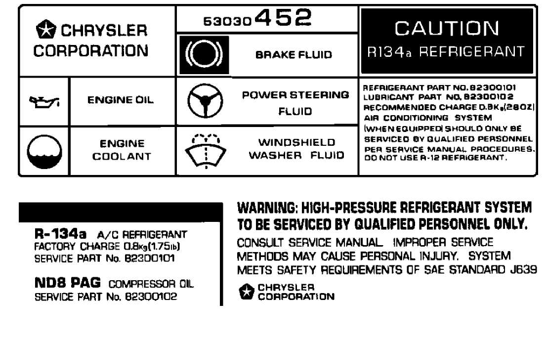
Underhood A/C Specification Labels
Most R-134a based systems will be identified through the use
of underhood labels with R-134a refrigerant clearly printed on labels. See Fig. 2. The underhood label used on Ford Motor Co. vehicles is Yellow. Most manufacturers will identify refrigerant type with labels affixed to compressor. Before servicing an A/C system, always determine which refrigerant is being used.
 93D28483
Fig. 2: Underhood Refrigerant Identification Labels Courtesy of Chrysler Corp.
(Chrysler)
Other Means Of Identification
Refrigerant R-134a, when viewed through a sight glass, may have a "milky" appearance due to the mixture of refrigerant and lubricating oil. As the refrigerant and oil DO NOT exhibit a "clear" sight glass on a properly charged A/C system, most R-134a systems have no sight glass.
REFRIGERANT OILS
Refrigerant R-12 based systems use mineral oil, while R-134a systems use synthetic/Polyalkylene Glycol (PAG) oils. Using a mineral oil based lubricant with R-134a will result in A/C compressor failure due to lack of proper lubrication.
Use only specified oil for the appropriate system and A/C compressor. Always check the underhood A/C specification label or A/C compressor label before adding refrigerant oil to A/C
compressor/system. See Fig. 2. The following R-134a refrigerant oils are currently available.
Jeep
Use PAG (ND8)
Refrigerant Oil (Part No. 82300102).
NOTE: Synthetic/PAG oils absorb moisture very rapidly, 2.3-5.6% by weight, as compared to a mineral oil absorption rate of .005% by weight.
SERVICE EQUIPMENT
NOTE: Ensure "O" rings are designed for use with specified refrigerant. Deterioration of "O" rings and system contamination will result if incorrect "O" rings are used.
Because R-134a is not interchangeable with R-12, separate sets of hoses, gauges and recovery/recycling equipment are required to service vehicles. This is necessary to avoid cross-contamination and damaging system.
All equipment used to service systems using R-134a must meet SAE standard J1991. The service hoses on the manifold gauge set must have manual (turn wheel) or automatic back-flow valves at the service port connector ends. This will prevent refrigerant from being released into the atmosphere.
For identification purposes, R-134a service hoses must have a Black stripe along their length and be clearly labeled SAE J2196/R-134a. The low pressure test hose is Blue with a Black stripe. The high pressure test hose is Red with a Black stripe. The center test hose is Yellow with a Black stripe.
NOTE: Refrigerant R-12 service hoses will ONLY be labeled SAE J2196.
R-134a manifold gauge sets can be identified by one or all of the following.
Labeled FOR USE WITH R-134a on set
Labeled HFC-134 or R-134a on gauge face
Light Blue color on gauge face
In addition, pressure/temperature scales on R-134a gauge sets are different from R-12 manifold gauge sets.
SIGHT GLASS INDICATOR
NOTE: Sight glass indicator conditions listed are for R-12
systems. Information for R-134a systems is not available from manufacturer.
Not all systems use a sight glass. If used, a sight glass may be mounted in receiver-drier (accumulator) or in discharge line. Refrigerant’s condition can be visually checked while passing through sight glass. The following are possible conditions of sight glass indicator, which may help in the diagnosis of problems. See Fig. 3.
Clear Sight Glass
A clear sight glass indicates refrigerant level is correct or is excessively low for system circulation. Sight glass may be clear, but system may contain excessive refrigerant. This must be verified by test gauge readings.
Bubbly/Foamy Sight Glass
A bubbly or foamy sight glass indicates system is low on refrigerant, and air has probably entered system. However, if only occasional bubbles are noticed, during clutch cycling or system startup, this may be a normal condition.
Oil Streaked Sight Glass
If oil streaks appear on sight glass, a lack of refrigerant may be indicated, and the system’s compressor oil is circulating through the system.
Cloudy Sight Glass
A cloudy sight glass indicates desiccant contained in
receiver-drier or accumulator has broken down and is being circulated through system.
Sight glass readings are not positive identification of a problem. Readings should be relied upon only when other system symptoms exist.
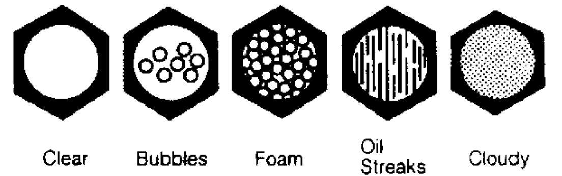
Fig. 3: Identifying Sight Glass Indicator Conditions
SYSTEM SERVICE VALVES
STEM-TYPE VALVES
This manually operated service valve has adjustable stem located under a protective cap. Valve stem must be manually positioned when making gauge connections and/or reading system pressure on the gauges. See Fig. 4.
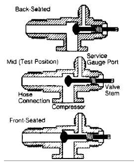
Fig. 4: Identifying Stem-Type Service Valve Positions
Back-Seated (Operating) Position
This is the normal operating position, which is also used for connecting and disconnecting manifold gauge set. Stem is turned fully
outward to seal the service gauge port.
Mid (Test) Position
After installing manifold gauge set (valve stem in back-seated position), turn valve stem 1 1/2 - 2 turns inward. This positions valve stem midway, allowing full system operation and permitting refrigerant pressure to reach gauges.
Front-Seated (Off) Position
With service valve stem turned inward, valve blocks refrigerant flow through system, isolating compressor for service.
CAUTION: NEVER operate A/C system with service valves in
front-seated position, as the compressor will be damaged.
SCHRADER-TYPE VALVES
NOTE: Although similar in construction and operation to a tire
valve, NEVER replace a Schrader-type valve with a tire valve.
Schrader valve is similar in construction and operation to a tire valve. When a test gauge hose is attached (hose has built-in valve core depressor), Schrader stem is pushed inward to the open position and allows system pressure to reach the gauge.
If test hose being used does not have a built-in core
depressor, an adapter must be used. Never attach hoses or adapters to a Schrader valve unless it is first connected to manifold gauge set.
SERVICE VALVE LOCATIONS
For service valve locations, see SERVICE VALCE LOCATIONS (TRUCKS & VANS) table.
SERVICE VALVE LOCATIONS TABLE (TRUCKS & VANS)
Vehicle High Low
Jeep
Cherokee & Wrangler (1) (1)
Grand Cherokee (1) (2)
- On A/C compressor.
- In suction line, near accumulator.
SPECIAL VALVE CONNECTORS
All vehicles with R-134a refrigerant use quick-disconnect service valves. To help prevent installing hoses and other parts used on R-12 systems, all fittings on R-134a systems use 1/2"-16 ACME threads.
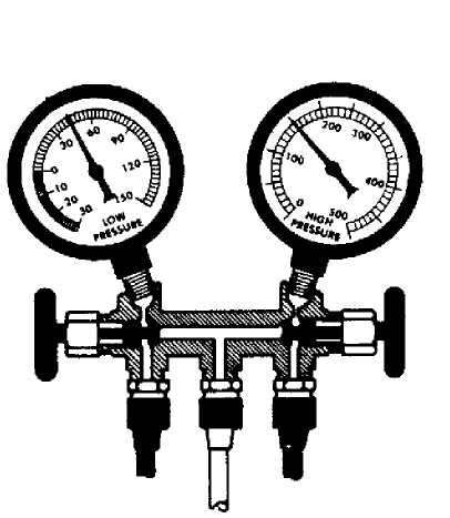
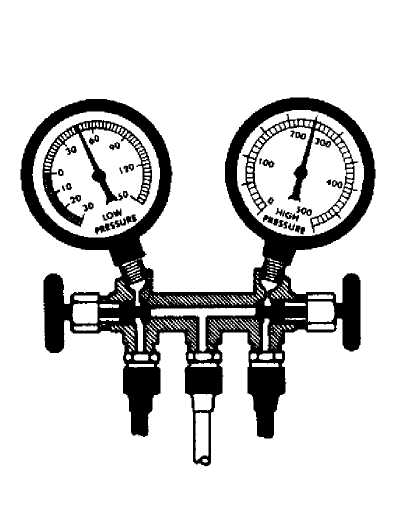
MANIFOLD GAUGE SET
A manifold gauge set is used to determine system’s high-side and low-side pressures, correct refrigerant charge, system diagnosis and operating efficiency. High (discharge) and low (suction) pressures must be compared to determine system operation. Manifold gauge sets for the two refrigerant types are basically the same. The fittings at the ends of the hoses are different to ensure connection only to a system using the type of refrigerant specified for that manifold gauge set.
Low-Side Gauge
The low-side gauge, which may have a Blue identifying feature, is used to measure low-side (suction) pressure. Low-side gauge is also called a compound gauge because it can measure pressure and vacuum. Pressure scale ranges from 0 to 150 psi; vacuum scale ranges from 0 to 30 in. Hg.
High-Side Gauge
The high-side gauge, which may have a Red identifying feature, is used to measure high-side (discharge) pressure. Gauge scale ranges from 0 to 500 psi.
CONNECTING GAUGE SET
Schrader-Type Valves
1) Put
on safety goggles, and cover vehicle’s fender. Remove
protective
caps from Schrader valves. Do this slowly to check for
leaky
valves.
CAUTION: Ensure hand valves on manifold gauge set are closed before connecting test hoses to Schrader valves.
Ensure
service hoses are equipped with valve core
depressor to match
Schrader valve. Special adapters are required if
service hoses do
not have built-in core depressor. Ensure both
manifold gauge hand
valves are closed.
Connect
low-side service hose to low-side (suction)
service valve, and
finger tighten connections. Connect high-side
service hose to
high-side (discharge) service valve, and finger
tighten
connections.
Stem-Type Valves
1) Put
on safety goggles, and cover vehicle’s fender. Place
valves
in back-seated position. Remove protective caps from service
valves.
Do this slowly to check for leaky valves.
CAUTION: Ensure hand valves on manifold gauge set are closed before turning service valve to mid-position.
2) Attach
low-side service hose to low-side (suction) service
valve. Connect
high-side service hose to high-side (discharge) service
valve.
Finger-tighten both connections.
NOTE: After test gauges are installed, test hoses must be purged of all air before proceeding with testing.
PURGING TEST HOSES
Ensure
high-side and low-side hoses are properly connected
to service
valves, and all hose connections are tight.
If
stem-type service valves are used, turn stems inward 1
1/2
- 2 turns to mid-position. On all applications,
place clean shop
towel over end of
center service hose.
Purge
high-side test hose by opening hand valve on high-
side
gauge for 3-5 seconds. This allows
system’s refrigerant to force
air
through test hoses and out of center service hose into the
shop
towel. Immediately close high-side gauge hand valve.
Purge
low-side test hose in the same manner using hand
valve of
low-side gauge. Close hand valve after 3-5 seconds.
Purging
of test hoses is now complete, and system is ready for
testing.
STABILIZING A/C SYSTEM
Once
manifold gauge set is attached to system and test
hoses have been
purged (if required), system is ready for
testing.
Place all test hoses, gauge
set and other equipment away from all
moving
parts of engine.
Start
engine, and turn A/C controls to maximum cooling
position. Set
blower fan on high speed. Open doors and/or windows, and
operate
system for 5-10 minutes. System should now
be stabilized and
ready for test
readings.
PRESSURE GAUGE INDICATIONS
NOTE: Pressure gauge indications are for R-12 systems only. Information for R-134a systems is not available from manufacturers.
The following typical pressure gauge indications represent conditions that may be encountered during system servicing. See Figs. 8-14. Temperature and humidity, as well as other factors, affect pressure gauge readings. Pressure gauge indications should be used only as a guide.
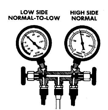
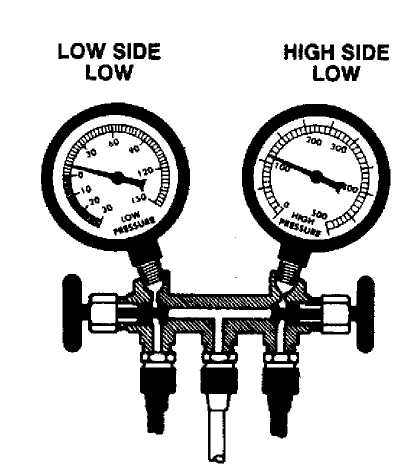
EXCESSIVE MOISTURE GAUGE READINGS
Low Side Gauge - Normal-to-Low High Side Gauge - Normal
Other Symptoms
Sight Glass - Tiny bubbles.
Discharge Air - Becomes warm as low side cycles into vacuum. As moisture is released by saturated desiccant, it becomes released by saturated desiccant, it becomes trapped and freezes at expansion valve or orifice tube, blocking R-12 flow into the evaporator. As low side drops to a vacuum, high side may rise.
EXCESSIVE MOISTURE
 GAUGE
READINGS
GAUGE
READINGS
Law Side Gauge - Normal-to-Low High Side Gauge - Normal
OTHER SYMPTOMS
SigM Glut - Tiny bubbles.
Discharge Air - Becomes warm as low side
cycles into vacuum. As moisture is released
by saturated desiccant, it becomes trapped
and freezes at expansion valve or orifice tube.
Slocking R-12 (low into me evaporator.
As low side drops to a vacuum, high side may rise.
CORRECTION
Discharge refrigerant from system.
Replace
receiver-drier,
accumulator or desiccant bag.
Evacuate system with vacuum pump.
Charge system with R-12.
Operate system and check performance.
Fig. 5: Excessive Moisture Pressure Gauge Indications Courtesy of Ford Motor Co.
Correction
Discharge refrigerant from system.
Replace receiver-drier, accumulator or desiccant bag.
Evacuate system with vacuum pump.
Charge system with R-12.
Operate system and check performance.
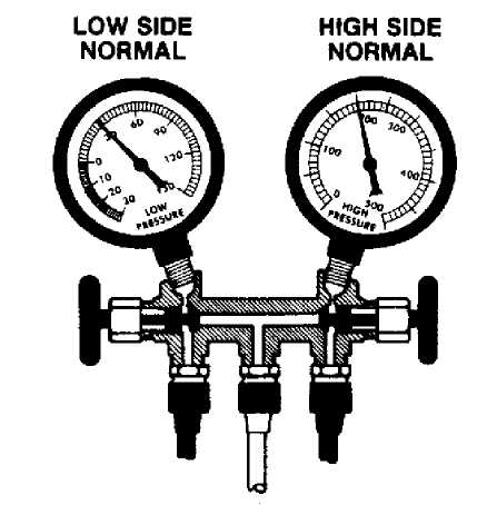
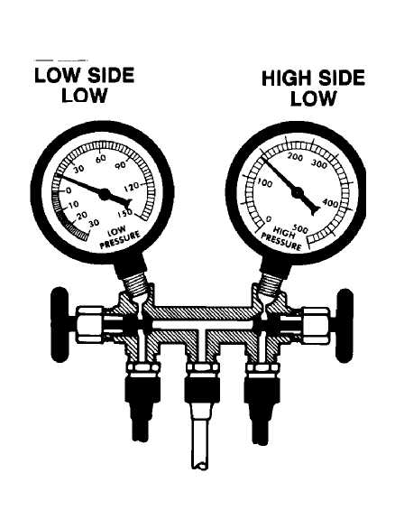
DEFECTIVE THERMOSTATIC SWITCH GAUGE READINGS
Low Side Gauge - Normal High Side Gauge - Normal
Other Symptoms
Compressor - Cycles on and off too fast.
Low Side Gauge - Not enough range shown on low side gauge.
DEFECTIVE THERMOSTATIC SWITCH
GAUGE
READINGS
Law Side Gauge - Normal High Side Gauge - Normal
OTHER SYMPTOMS
Compressor - Cycles on and off too fast.
Low Side Gauge - Not enough range shown on low side gauge.
CORRECTION
Stop
vehicle engine and
turn air conditioner "OFF".
Remove
and discard old
clutch cycling switch, install a
new switch
of same type,
Operate system and check performance.
Fig. 6: Defective Thermostatic Switch Pressure Gauge Indications Courtesy of Ford Motor Co.
Correction
Stop vehicle engine and turn air conditioner "OFF".
Remove
and discard old clutch cycling switch, install a
new switch of
same type.
Operate system and check performance.
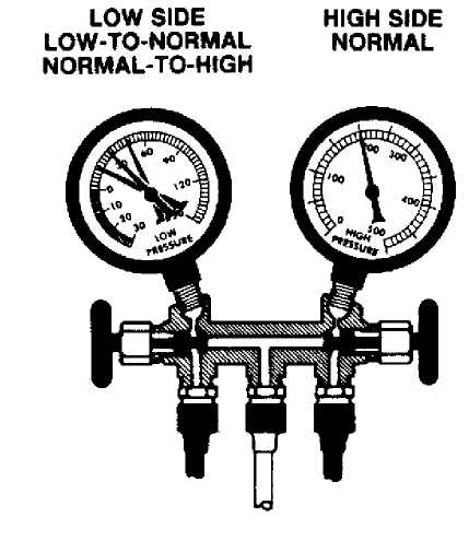
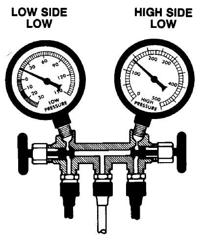
MISADJUSTED THERMOSTATIC SWITCH GAUGE READINGS
See DEFECTIVE CLUTCH CYCLING SWITCH PRESSURE GAUGE READINGS below.
DEFECTIVE CLUTCH CYCLING SWITCH PRESSURE GAUGE READINGS
Low Side Gauge - Low-to-Normal/Normal-to-High High Side Gauge - Normal
Other Symptoms
Compressor - Cycles at incorrect temperature or pressure.
Evaporator - May freeze and restrict airflow if switch is allowing compressor to remain on too long.
MISADJUSTED THERMOSTATIC SWITCH OR DEFECTIVE CLUTCH CYCLING SWITCH
GAUGE READINGS
Low Side Gauge - Low-to-Normal/Norma(-to-High High Side Gauge - Normal
OTHER SYMPTOMS
Compressor - Cyctes at incorrect temperature or pressure.
Evaporator - May freeze and restrict airflow
if switch 15 allowing compressor to remain on too long.
CORRECTION
With Thermottatie Switch
1) Stop engine and turn air conditioner off.
2} Remove components necessary to gain access to thermostatic adjustment screw.
NOTE: If no adjusting screw is provided, the switch it Ronedjuatable end must be replaced.
3} Make certain that all wiring Is positioned so that no short-circuiting can occur. Connect battery ¸đ█ő so that engine can be operated while making switch adjustment. Adjust thermostatic switch.
With Clutch Cycling Switch
1) Stop engine and turn air conditioner oil.
NOTE: Switch it nonedjuttable and it mounted on a Schrader valve fitting. Therefore, no system discharge is required,
Detach
electrical connector from
pressure sensing switch at
accumulator.
Remove
pressure sensing switch,
and install a new switch.
NOTE: A pressure sensing-mritch is used on most late
Ford Motor Co., General Motors and Eagle model» with accumulator-type systems. It perform* the same (unction as trrarmoslailc switch.
Fig. 7: Misadjusted Thermostatic Switch or Defective Clutch Cycling Switch Gauge Indications Courtesy of Ford Motor Co.
Correction With Thermostatic Switch
NOTE: If no adjusting screw is provided, the switch is nonadjustable and must be replaced.
Stop engine and turn air conditioner off.
Remove
components necessary to gain access to thermostatic
adjustment
screw.
Make
certain that all wiring is positioned so that no
short-circuiting
can occur.
Connect battery cable so that engine can be operated while making switch adjustment.
Adjust thermostatic switch. Correction With Clutch Cycling Switch
NOTE: Switch is non adjustable and is mounted on a Schrader valve fitting. Therefore, no system discharge is required.
Stop engine and turn air conditioner off.
Detach
electrical connector from pressure sensing switch
at accumulator.
Remove pressure sensing switch, and install a new switch.
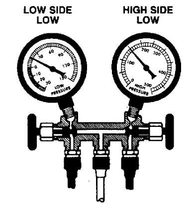
LOW R-12 CHARGE GAUGE READINGS
Low Side Gauge - Low High Side Gauge - Low
Other Symptoms
Discharge Air - Slightly cool. Sight Glass - Some bubbles.
LOW R-12 CHARGE
GAUGE
READINGS
Low Side Gauge - Low High Side Gauge - Law
OTHER SYMPTOMS
Discharge Air - Slightly cool. Sight Glass - Some bubWes.
CORRECTION
Leak test system.
Discharge
refrigerant from system if
necessary to replace units or lines.
Repair leaks.
Check compressor oil level.
System may have lost oil due to leakage.
Evacuate system using vacuum pump.
Charge system with R-12.
Operate system and check performance.
Fig. 8: Low R-12 Charge Pressure Gauge Indications Courtesy of Ford Motor Co.
Correction
Leak test system.
Discharge
refrigerant from system if necessary to replace
units or lines.
Repair leaks.
Check
compressor oil level. System may have lost oil due
to leakage.
Evacuate system using vacuum pump.
Charge system with R-12.
Operate system and check performance.
VERY LOW R-12 CHARGE GAUGE READINGS
Low Side Gauge - Low High Side Gauge - Low
Other Symptoms
Discharge Air - Warm.
Sight Glass - Clear or Oil Streaks.
Compressor - Operation may have stopped if system is equipped
with a refrigerant pressure sensing switch.
VERY LOW R-12 CHARGE
GAUGE
READINGS
Low Side Gauge - Low High Side Gauge - Low
OTHER SYMPTOMS
Discharge Air - Warm.
Sight Glass - Clear or Oil Streaks.
Compressor - Operation may have stopped if system is equipped with a refrigerant pressure sensing switch.
CORRECTION
if
compressor operation is stopped
due to a pressure sensing
switch,
by-pass switch with jumper wire until
lasting and
correction are complete.
Add a partial refrigerant charge
(to at least 50 percent system capacity), !hen make thorough leak test.
Discharge refrigerant from system.
Check compressor oil level.
System may have lost oil due to leakage.
Evacuate system using vacuum pump.
Charge system with fl-12.
Operate system and check performance.
Fig. 9: Very Low R-12 Charge Pressure Gauge Indications Courtesy of Ford Motor Co.
Correction
If
compressor operation is stopped due to a pressure
sensing
switch, by-pass switch with jumper wire until
testing and
correction are complete.
Add
a partial refrigerant charge (to at least 50 percent
system
capacity), then make thorough leak test.
Discharge refrigerant from system.
Check
compressor oil level. System may have lost oil due
to leakage.
Evacuate system using vacuum pump.
Charge system with R-12.
Operate system and check performance.
EXPANSION OR "H" VALVE STUCK CLOSED GAUGE READINGS
Low-Side Gauge - Low High-Side Gauge - Low
Other Symptoms
Discharge Air - Slightly cool
Evaporator Inlet Pipe - Sweating or frost build up
Testing
1) If evaporator inlet is cool to touch, proceed as follows:
a. Set air conditioner for maximum
cooling,
and operate the system.
b. Spray
liquid R-12 on head of valve or capillary tube
(if
equipped). Note low-side gauge reading.
Low-side
gauge should drop into a vacuum.
c. If low-side vacuum reading was obtained,
warm expansion
valve diaphragm chamber with hand, then repeat
test
step b.
d. If expansion valve test indicates valve
operation is
satisfactory, clean contact surface of
evaporator
outlet pipe and temperature sensing bulb. Ensure
bulb
is securely in contact with pipe.
e. If expansion valve test indicates the valve
is
defective, discharge the system, replace expansion
valve,
and proceed with correction procedure.
2) If
expansion valve inlet shows sweating or frost proceed
as
follows:
a. Discharge system.
b. Disconnect inlet line at expansion valve.
Remove and
inspect screen.
c. Clean and replace screen, and reconnect inlet line.
d. Proceed with correction procedure.
EXPANSION OR "H" VALVE STUCK CLOSED
GAUGE
READINGS
Low Side Gauge - Low High Side Gauge - Low
OTHER SYMPTOMS
Discharge Air - Slightly cool
Evaporator Inlet Pipe - Sweating or frost build up
TESTING
1) If evaporator inlet is
cool to touch, proceed as follows:
a. Set
air conditioner for maximum
cooling and operate the system.
b. Spray
liquid R-12 on head of valve
or capillary tube (if equipped). Note
low side gauge reading. Low side gauge should drop into a vacuum.
¸ If low side vacuum reading was obtained,
warm expansion valve diaphragm chamber with hand, then repeat test step b.
d. If expansion valve test indicates valve operation
is satisfactory, clean contact surface of evaporator outlet pipe and temperature sensing bulb. Make sure bulb is securely in contact with pipe.
e. If
expansion valve test indicates
the valve is defective, discharge
the system, replace expansion valve, and proceed with correction procedure.
2) If
expansion valve inlet shows sweating
or
frost proceed as follows:
a. Discharge system.
b. Disconnect
inlet line at expansion valve.
Remove and inspect screen.
¸ Clean and replace screen and reconnect inlet line. d. Proceed with correction procedure.
CORRECTION
Evacuate system using vacuum pump.
Charge system with R-12.
Operate system and check performance.
104008
Fig. 10: Expansion or "H" Valve Stuck Closed Courtesy of Ford Motor Co.
Correction
Evacuate system using vacuum pump.
Charge system with R-12.
Operate system and check performance.
ORIFICE TUBE PLUGGED GAUGE READINGS
Low Side Gauge - Low High Side Gauge - Low
Other Symptoms
Discharge Air - Slightly cool.
Evaporator Inlet Pipe - Sweating or frost build up just ahead
of orifice tube.
Testing
If evaporator inlet pipe after orifice tube and accumulator surface are warm, orifice tube is plugged.
ORIFICE TUBE PLUGGED
GAUGE
READINGS
Low Side Gauge - Low High Side Gauge - Low
OTHER SYMPTOMS
Discharge Air - Slightly cool
Evaporator Inlet Pipe - Sweating or frost build up just ahead of orifice tube.
TESTING
If evaporator inlet pipe
after orifice tube and accumulator
surface are warm, orifice tube is plugged.
CORRECTION
Evacuate system using vacuum pump.
Replace orifice tube.
Charge system with R-12.
Operate system and check performance.
104009
Fig. 11: Orifice Tube Plugged Pressure Courtesy of Ford Motor Co.
Correction
Gauge Indications
Evacuate system using vacuum pump.
Replace orifice tube.
Charge system with R-12.
Operate system and check performance.
EXPANSION OR "H" VALVE STUCK OPEN GAUGE READINGS
Low Side Gauge - High High Side Gauge - High
Other Symptoms
Discharge Air - Warm Evaporator - Sweating or frost.
Testing
Check for expansion valve stuck open, or incorrect mounting of temperature sensing bulb as follows:
a. Set air conditioner for maximum cooling and
operate
system several minutes.
b. Spray liquid R-12 on head of valve or
capillary bulb, and
note low side gauge reading. It should drop
into a vacuum
(if not, a stuck open valve or incorrect bulb mounting is
indicated). This test may not be possible on applications where sensing bulb is not accessible.
c. If low side vacuum reading is obtained, warm expansion valve diaphragm chamber with hand, then repeat test.
EXPANSION OR "H" VALVE STUCK OPEN
Indications
Low SkM Gauge - High High Side Gauge - High
OTHER SYMPTOMS
Dlscharg* Air - Warm Evaporator - Sweating or frost.
TESTING
Check for expansion valve stuck open, or incorrect mounting of temperature sensing bulb as follows:
a. Set
air conditioner lor maximum cooling
and operate system several
minutes.
b. Spray
liquid R-12 on head of valve or
capillary bulb, and note low side
gauge reading.
It should drop into a vacuum (if not, a stuck
open
valve oc incorrect bulb mounting is indicated).
This test
may not be possible on applications
where sensing bulb is not
accessible.
c. if
low side vacuum reading is obtained,
warm expansion valve
diaphragm chamber
with hand, then repeat test.
CORRECTION
1) If expansion valve test indicates valve operation is satisfactory, proceed as follows:
a. Clean
contact surface of evaporator outlet
pipe and temperature sensing
bulb, then clamp
bulb securely in contact with pipe and
recover
with proper insulation tape.
b. Operate system and check performance.
12: Expansion or "H" Valve Stuck Open Pressure Gauge
Fig.
Courtesy of Ford Motor Co. Correction
2) If expansion valve test indicates valve is defective, proceed as Follows:
a. Discharge system.
b. Replace
expansion valve, making sure
all contacts are clean and secure.
c. Evacuate
system using vacuum pump,
then charge system with R-12.
d. Operate system and check performance.
1) If
expansion valve test indicates valve operation is
satisfactory,
proceed as follows:
a. Clean contact surface of evaporator outlet
pipe and
temperature sensing bulb, then clamp bulb securely
in
contact with pipe and recover with proper insulation
tape.
b. Operate system and check performance.
2) If
expansion valve test indicates valve is defective,
proceed as
follows:
a. Discharge system.
b. Replace expansion valve, making sure all
contacts are
clean and secure.
c. Evacuate system using vacuum pump, then
charge system
with R-12.
d. Operate system and check performance. COMPRESSOR MALFUNCTION GAUGE READINGS
Low Side Gauge - High High Side Gauge - Low
Other Symptoms Compressor - Noisy.
gauge READINGS COMPRESSOR MALFUNCTION
Low Ski» Gauge - High
Hieh3«.G.ofl.-Lo* LOW SIDE HIGH SIDE
OTHER SYMPTOMS HIGH LOW
Compressor - Noisy.
CORRECTION
1) Isolate compressor (If equipped with
stem-type service valves) or discharge entire system.
2) Remove compressor cylinder head and Inspect compressor.
a. Replace reed valve plate assembly if necessary.
b. Install cylinder head using NEW gasket.
Check compressor oil leva*.
Replace receiver-drter. desiccant or accumulator If:
a. System previously opened.
b. System operated two or more seasons with present unit.
c. Compressor
Inspection revealed desiccant particles
(very fine golden or brown
particles).
Using
vacuum pump, evacuate compressor or entire
system (depending on
procedure used in step 1».
Charge system wrtti R-12.
Operate system and check performance.
Fig. 13: Compressor Malfunction Pressure Gauge Indications Courtesy of Ford Motor Co.
Correction
Isolate
compressor (if equipped with stem-type service
valves) or
discharge entire system.
Remove compressor cylinder head and inspect compressor.
a. Replace reed valve plate assembly if necessary.
b. Install cylinder head using NEW gasket.
Check compressor oil level.
Replace receiver-drier, desiccant or accumulator if:
a. System previously opened.
b. System operated two or more seasons with present unit.
c. Compressor inspection revealed desiccant particles
(very fine golden or brown particles).
5) Using vacuum pump, evacuate compressor or entire system
(depending on procedure used in step 1).
Charge system with R-12.
Operate system and check performance.
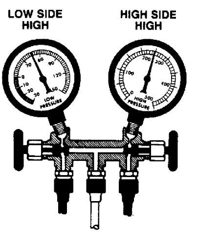
CONDENSER MALFUNCTION OR R-12 OVERCHARGE GAUGE READINGS
Low Side Gauge - High High Side Gauge - High
Other Symptoms
Discharge Air - Warm.
High Side Lines - Very Hot.
Sight Glass - Bubbles.
CONDENSER MALFUNCTION OR R-12 OVERCHARGE
GAUGE READINGS
Low Side Gauge - High High Side Gauge - High
OTHER SYMPTOMS
Discharge Air - Warm,
High Side Lines - Very Not.
Sight Glass - Bubbles. LOW SIDE HIGH SIDE
CORRECTION HIGH HtGH
Check electric cooling fan operation.
Inspect
condenser for clogged air passages.
bug screen, or other
obstructions preventing
airflow through condenser.
inspect
condenser mounting for proper
radiator clearance, inspect clutch
type fan for
proper operation. Inspect radiator pressure cap
for
correct type and proper operation.
After Making Above Correction*
Operate system and check performance. If Condition is Not Corrected
1) Inspect system for overcharge
of refrigerant and correct as follows:
a. Discharge
refrigerant until stream of
bubbles appears in sight glass and
both
high and low gauge readings drop below normal.
b. Add
R-12 until bubbles disappear and
pressures are normal, then add
an
additional 1/4-1/2 Ib.
of refrigerant.
2) Operate
system and check performance,
If
Gauge Readings Still Too High
1) Discharge
system, and remove and inspect
condenser
to ensure free passage
of refrigerant or replace condenser.
Repiace receiver-drier, desiccant bag or accumulator.
Evacuate system using vacuum pump.
Charge system with R-12.
Operate system and check performance.
Fig. 14: Condenser Malfunction or R-12 Overcharge Pressure Gauge
Indications
Courtesy of Ford Motor Co.
Correction
Check electric cooling fan operation.
Inspect
condenser for clogged air passages, bug screen, or
other
obstructions preventing airflow through condenser.
Inspect
condenser mounting for proper radiator clearance.
Inspect clutch
type fan for proper operation. Inspect
radiator pressure cap for
correct type and proper
operation.
After Making Above Corrections. Operate system and check performance. If Condition is Not Corrected.
1) Inspect
system for overcharge of refrigerant and correct
as
follows:
a. Discharge refrigerant until stream of
bubbles appears
in sight glass and both high and low gauge
readings
drop below normal.
b. Add
R-12 until bubbles disappear and pressures are
normal,
then add an additional 1/4-1/2 lb.
of
refrigerant.
2) Operate
system and check performance. If Gauge Readings
Still Too High
a. Discharge system, and remove and inspect
condenser to
ensure free passage of refrigerant or
replace
condenser.
b. Replace receiver-drier, desiccant bag or accumulator.
c. Evacuate system using vacuum pump.
d. Charge system with R-12.
e. Operate system and check performance.
JEEP
The orifice tube is located in the liquid refrigerant line near the condenser. Orifice tube cannot be replaced as a separate component. If orifice tube is faulty or if compressor is replaced, liquid line must be replaced.
REFRIGERANT RECOVERY/RECYCLING
NOTE: The use of recovery/recycling equipment is required by law.
Refrigerant recovery/recycling equipment is used to remove refrigerant from vehicle’s A/C system without polluting atmosphere. To remove and recycle refrigerant, ALWAYS follow instructions provided with the refrigerant/recovery equipment being used.
The removed refrigerant is filtered, dried and stored in a tank within the recovery/recycling equipment until it is ready to be pumped back into the vehicle’s A/C system.
NOTE: Separate sets of hoses, gauges and refrigerant
recovery/recycling equipment MUST be used for R-12 and R-134a based systems. DO NOT mix R-12 and R-134a refrigerants, as their refrigerant oils and desiccants are NOT compatible.
Manufacturer recommends using refrigerant recovery/recycling equipment which meets SAE standard J1991. Always use instructions provided with the recovery/recycling equipment being used.
DISCHARGING A/C SYSTEM
NOTE: When discharging refrigerant from A/C system, use
refrigerant recovery/recycling equipment to prevent refrigerant from entering the atmosphere. The use of recovery/recycling equipment is required by law.
Manufacturer does not provide procedures for discharging A/C system. Discharge A/C system using approved refrigerant recovery/recycling equipment. Follow instructions provided with
recovery/recycling equipment for recovery and recycling of refrigerant.
FLUSHING A/C SYSTEM
Information is not available from manufacturer.
EVACUATING A/C SYSTEM
CHRYSLER CORP.
Close both
valves on manifold gauge set. Connect manifold
gauge set to
high-side and low-side service valves. See SERVICE VALVE
LOCATIONS
under SYSTEM SERVICE VALVES. Connect a hose to center
connector
on manifold gauge set and evacuation pump.
Fully open both valves on manifold gauge set. Start
evacuation pump, and operate it until a vacuum reading of 2 6 in. Hg is obtained on low-side gauge. If vacuum reading of 2 6 in. Hg cannot be reached,either A/C system or gauge set leaks, or evacuation pump is defective. Repair or replace as necessary.
When
specified vacuum reading has been reached, close both
valves
on manifold gauge set. Turn off evacuation pump. Observe low-
side
gauge. If vacuum drops within 30 minutes,
system has a leak and
must be repaired.
If
vacuum remains steady, reopen valves, and continue
operating
evacuation pump for an additional 10 minutes.
Close both
valves, and stop evacuation pump.
CHARGING A/C SYSTEM
NOTE: Manufacturer does not recommend using one-pound cans. Using a charging station will allow precise measurement of refrigerant charge. See REFRIGERANT OIL & REFRIGERANT SPECIFICATIONS at the end of this article for system capacities.
System
must be evacuated before charging. With manifold
gauge set
attached from evacuation procedures, attach refrigerant
container(s)
to hose on center connector of manifold gauge set. Fully
open
refrigerant container valve(s), purge air from center hose,
and
close valves.
Adjust
service valves on the compressor to the mid-
position (if
equipped). Slowly open low-side valve, and
allow
refrigerant to enter the system.
Start and operate engine. Place A/C
heater controls to
maximum cold position.
When
proper amount of refrigerant has been added, close
low-side valve
on manifold gauge set. Stop engine, close service
valves
on compressor, and disconnect manifold gauge set. Start engine,
and
operate A/C system for 10 minutes to
stabilize the system.
LEAK TESTING
Operate system to stabilize high-side and low-side pressures. Turn engine off. Using a refrigerant leak detector, check all refrigerant line connections for leaks. Check compressor seal area and condenser.
Refrigerants are heavier than air. Always check for leaks at bottom of refrigerant lines and components. Refrigerant oil will leak with refrigerant. Visually check all connections and compressor clutch area for oil stains. If compressor shaft seal is leaking, a fresh oil
streak will normally be seen on underside of hood, above compressor clutch.
Always perform leak testing after A/C service. Move
refrigerant leak detector slowly to check for leaks, as leaks will not be detected if leak testing is performed too quickly.
REFRIGERANT OIL & REFRIGERANT SPECIFICATIONS
NOTE: Due to late changes, always refer to underhood A/C
Specification Label in engine compartment or A/C compressor label while servicing A/C system. If A/C Specification Label and specifications in table differ, use label specifications.
REFRIGERANT OIL & REFRIGERANT CAPACITY TABLE (LIGHT TRUCKS & VANS)
(1) Oil Refrigerant
Application Ounces Ounces
Jeep
Cherokee 4.6 38
Grand Cherokee (2) 8.0 28
Wrangler 4.6 32
- Total system capacity, unless otherwise noted.
- Models use R-134a refrigerant and PAG (ND8) Refrigerant Oil
(Part No. 82300102).
COMPRESSOR APPLICATIONS
NOTE: Due to late changes, always refer to underhood A/C
Specification Label in engine compartment or A/C compressor label while servicing A/C system. If A/C Specification Label and specifications differ, use label specifications.
COMPRESSOR APPLICATIONS TABLE (LIGHT TRUCKS & VANS)
Application Compressor
Jeep
Cherokee & Wrangler Sanden SD-709 7-Cyl.
Grand Cherokee Nippondenso 10PA17 10-Cyl.
(1) - Series codes are determined by fifth character of VIN code.