Ā
1993 Jeep Cherokee
Fuses & Circuit Breakers 1993-95 Jeep
Jeep; Cherokee
IDENTIFICATION
FUSES & CIRCUIT BREAKERS
The fuse block is to the left of the steering column, under the instrument panel.
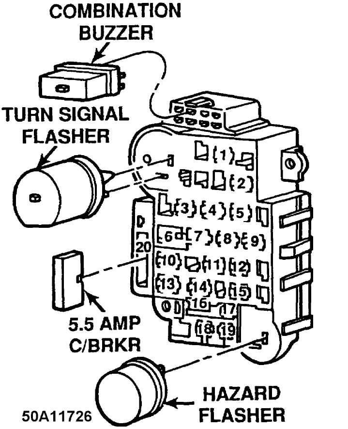
Fig. 1: Fuse Panel Identification (1993-95) Courtesy of Chrysler Corp.
FUSE & CIRCUIT BREAKER I.D. (PASSENGER COMPARTMENT)
1-25 Amp (Natural)
Rear Window Wiper, Washer.
2-15 Amp (Lt. Blue)
Radio, Cigar Lighter, Dome Lamp (1993) .
3 - Not Used Not Used.
4-15 Amp (Lt. Blue) Flash to Pass.
5-25 Amp (Natural) (1992) Blower Motor.
6-30 Amp (Circuit Breaker) Power Windows.
7-2 Amp (Pink) Antilock Brakes (ABS).
8-20 Amp (Yellow) Turn Signal Flasher.
9-10 Amp (Red)
Radio/Clock & Memory, Courtesy Lights, Glove Box, Cargo, Dome Lamps, Telltales.
- Not Used
Not Used.
- 25 Amp (Natural)
Headlamp Delay Module, Horns.
- Not Used
Not Used.
- 20 Amp (Yellow)
Power Door Locks.
- Not Used
Not Used.
- 15 Amp (Lt. Blue)
Instrument Panel Lamps, Clock, Radio/Clock & Memory, Headlamp Switch, Parking Lamps.
- 30 Amp (Circuit Breaker)
Power Seats, Trailer Tow.
- 7.5 Amp (Violet)
Instrument Cluster Guages, Headlamp Delay Module, Chime Module, Overhead Console.
18 - 25 Amp (Natural)
Heated Rear Window.
19-5 Amp (Tan)
Instrument Panel Lamps, Radio Illumination.
20 - 5.5 Amp (Circuit Breaker) Windshield Wiper/Windshield Washer.
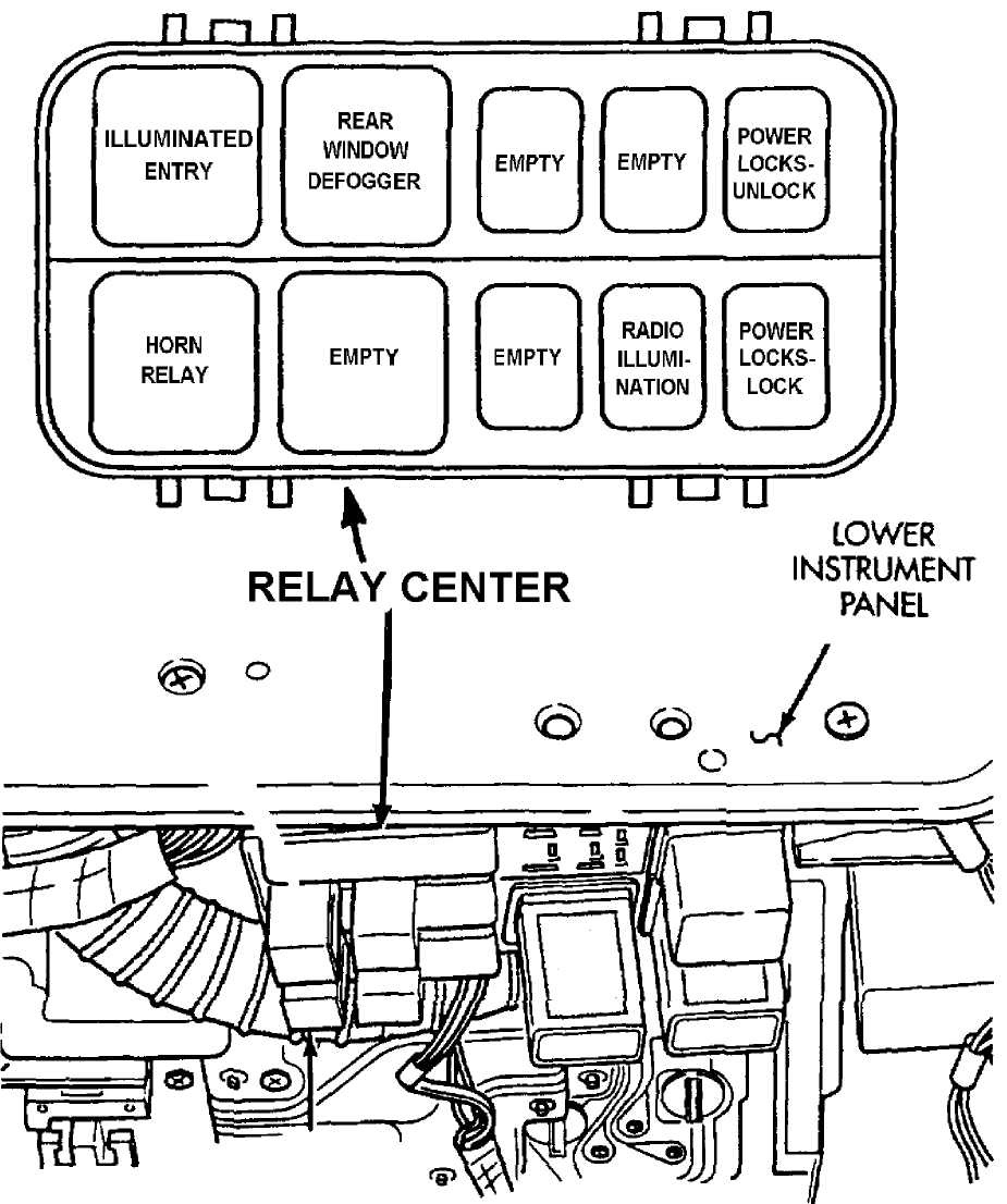
RELAY PANEL IDENTIFICATION (1993-95 MODELS)
The relay panel is to the right of the steering column, under the instrument panel.
50B11727
Fig. 2: Relay Block Identification (1993-95 Models) Courtesy of Chrysler Corp.
RELAY IDENTIFICATION (PASSENGER COPMPARTMENT)
- Illuminated Entry Relay (1993-94); Not Used (1995)
No additional definition.
- Horn Relay (1993-94); Dual Flasher Relay (1995)
No additional definition.
- Rear Window Defogger Relay
No additional definition.
- Not Used
No additional definition.
- Not Used (1993-94); Horn Relay (1995)
No additional definition.
- Not Used
No additional definition.
7 - Not Used
No additional definition.
8 - Radio Illumination Relay
No additional definition.
9 - Power Door Lock (Unlock) Relay
No additional definition.
10 - Power Door Lock (Lock) Relay
No additional definition.
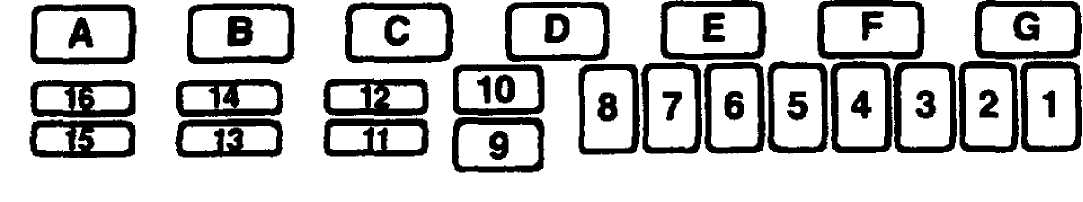
POWER DISTRIBUTION CENTER IDENTIFICATION (1993-95)
50C11652
Fig. 3: Power Distribution Center Identification (1993-95) Courtesy of Chrysler Corp.
WARNING: Always disconnect battery ground cable before servicing
"high-current fuses. It is recommended that "high-current" fuses be replaced by a qualified technician.
FUSE & CIRCUIT BREAKER I.D. (POWER DISTRIBUTION)
1-60 Amp (Blue) Generator Output.
2-30 Amp (Green)
Engine Control (ECU) - Fuel Pump, Injectors, Ignition Coil, Oxygen Sensors, Generator Field, Engine Controller Automatic Transmission Controller (ATCU).
3-40 Amp (Orange) Fuse Block.
4-20 Amp (Yellow)
Hazard Lamps.
5-40 Amp (Orange) Headlamp Switch.
6-50 Amp (Red)
Ignition Switch - Engine Controller, Fuel Pump Relay, Automatic Shutdown Relay Coil.
7-40 Amp (Orange)
Heated Rear Window, Starter Solenoid.
8-40 Amp (Orange) ABS Pump Motor.
9-60 Amp (Blue) Generator Output.
- 30 Amp (Green)
ABS System.
- 15 Amp (Blue)
Ignition Switch - Back-up Lamps, A/C Relay Coil, Shift Selector, Speed Control, Aux. Cooling Fan Relay Coil.
- 10 Amp (Red)
Automatic Transmission.
- 15 Amp (Blue)
Auxilliary Lamps - Fog Lamps, Underhood Lamps.
- 20 Amp (Yellow)
Engine Controller.
- 20 Amp (Yellow)
Aux. Cooling Fan.
- 10 Amp (Red)
Ignition Off Draw (1993), Radio/Clock Memory, Ignition Off Draw, Dome Courtesy (1994-95).
RELAY IDENTIFICATION (POWER DISTRIBUTION)
A - Aux. Cooling Fan Relay
B - Fuel Pump Relay
C - ABS Pump Relay
D - Air Conditioning Relay
E - Auto Shutdown Relay
F - Starter Relay
G - ABS System Relay
CAUTIONS & WARNINGS
BATTERY
WARNING: When battery is disconnected, vehicles equipped with computers may lose memory data. When battery power is restored, driveability problems may exist on some vehicles. These vehicles may require a relearn procedure. See the COMPUTER RELEARN PROCEDURES article in GENERAL INFORMATION section.
SUPPLEMENTAL RESTRAINT (AIR BAG SYSTEM) (IF EQUIPPED)
WARNING: The Diagnostic Energy Reserve Module (DERM) can maintain
enough voltage to cause a deployment of the Inflator Module for up to 10 minutes after the Ignition Switch is turned off and the battery is disconnected. Many of the service procedures require disconnection of the Inflator Module to avoid an accidental deployment.