Ā
1993 Jeep Cherokee
1993 ACCESSORIES & EQUIPMENT Chrysler Corp. Power Mirrors
Jeep; Cherokee, Grand Cherokee, Grand Wagoneer
DESCRIPTION & OPERATION
Cherokee
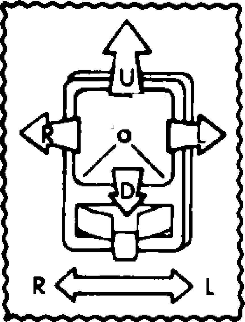
Mirror control switch contains 2 separate switches: operating switch and selector switch. Each mirror has 2 reversible motors. Driver operates 3 switches that control polarity of voltage to motors. Mirror select switch directs these controlled voltages to desired mirror.
Grand Cherokee & Grand Wagoneer
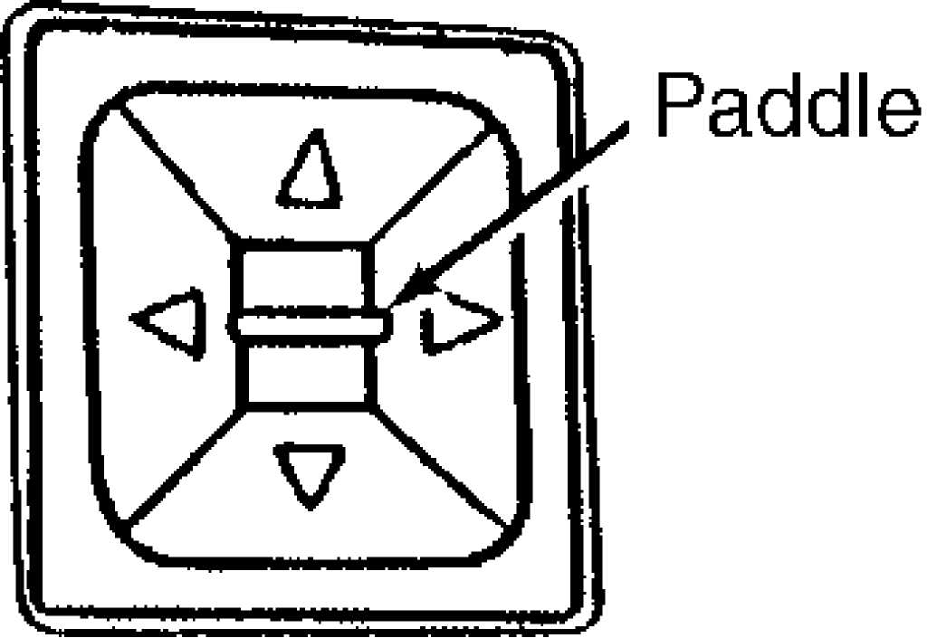
Switches for mirror selection and operation are combined in a single assembly. Central paddle in switch assembly selects mirror to be adjusted when moved to the right or the left. Adjustment is made by pressing the buttons surrounding the central paddle. These buttons control polarity of voltage to 2 motors within each mirror which adjust mirror up, down, right and left as desired.
TESTING
POWER MIRROR SWITCH
Remove power mirror switch. See POWER MIRROR SWITCH in
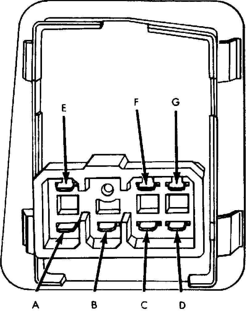
REMOVAL & INSTALLATION. Place selector switch in right or left mirror mode. Using ohmmeter, check for resistance at appropriate terminals when each operation switch is activated. See POWER MIRROR SWITCH CONTINUITY TEST. See Figs. 1-4. If continuity is not as specified, power mirror switch must be replaced as an assembly.
POWER MIRROR SWITCH CONTINUITY TEST TABLE (CHEROKEE)
Switch Position Pin Continuity
Left mirror
Up A & F, E & G
Down A & G, E & F
Right B & F, E & G
Left B & G, E & F
Right Mirror
Up D & F, E & G
Down D & G, E & F
Right C & F, E & G
Left C & G, E & F
/
Fig. 1: Identifying Power Mirror Switch (Cherokee) Courtesy of Chrysler Corp.
Power Mirror Switch Assembly
Fig. 2: Identifying Power Mirror Switch Terminals (Cherokee) Courtesy of Chrysler Corp.
POWER MIRROR SWITCH CONTINUITY TEST TABLE (EXCEPT CHEROKEE)
Switch Position Pin Continuity
Left mirror
Up 6 & 8; 5, 1 & 4
Down 6 & 1; 5 & 8
Right 6 & 1; 5 & 4
Left 6 & 4; 5, 1 & 8
Right Mirror
Up 6 & 7; 5, 1 & 3
Down 6 & 1; 5 & 7
Right 6 & 1; 5 & 3
Left 6 & 3; 5, 1 & 7
93C76432
Fig. 3: Identifying Power Mirror Switch (Except Cherokee) Courtesy of Chrysler Corp.
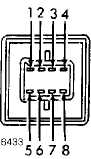
Fig. 4: Identifying Power Mirror Switch Terminals (Except Cherokee) Courtesy of Chrysler Corp.
POWER MIRROR MOTOR
Remove door trim panel. Unplug harness connector. Connect a jumper wire to 12-volt power source. Connect another jumper wire to good body ground. Connect jumper wires to appropriate pin numbers. See POWER MIRROR MOTOR TEST table. See Fig. 5. If mirror reaction is not as specified, replace mirror assembly.
POWER MIRROR MOTOR TEST TABLE
|
12 Volts |
Grc |
)unc |
|
|
Pin No. |
3 |
Pin |
No |
|
Pin No. |
1 |
Pin |
No |
|
Pin No. |
3 |
Pin |
No |
|
Pin No. |
2 |
Pin |
No |
|
Pin No. |
6 |
Pin |
No. |
Mirror Reaction
1 Up
3 Down
2 Right
3 Left
5 Heater
93E76434
 Fig. 5: Identifying Power Mirror Connector Terminals Courtesy of Chrysler Corp.
REMOVAL & INSTALLATION
POWER MIRROR ASSEMBLY
NOTE: When removing door trim panel, start at bottom of panel. Pry panel free with wide, flat prying instrument.
Removal & Installation (Cherokee)
Remove interior door latch release assembly and control
panel retaining screws. Disconnect control linkage and wire harness
connector. Remove latch release and control panel assembly. Remove
armrest lower retaining screws.
Swing armrest downward to a vertical position. Disconnect
armrest from upper retainer clip. Pull armrest straight out from trim
panel. Remove trim panel.
Remove screw holding mirror trim cover. Disconnect power
mirror wire harness at connector in door. Pull harness up through
door. Remove 3 screws holding mirror to door. To install, reverse
removal procedure.
Removal & Installation (Except Cherokee)
Remove screws from demister opening armrest. Remove door handle cover screws. Remove door trim panel. Unplug mirror harness at connector. Remove 3 mounting nuts. Remove mirror. To install, reverse removal procedure
POWER MIRROR SWITCH
Removal & Installation (Cherokee)
Using a wide, thin flat blade tool, such as a putty knife, pry one side of switch housing away from center console. Remove switch from console. Carefully disconnect harness connector. To install, reverse removal procedure.
Removal & Installation (Except Cherokee)
Disconnect negative battery cable. Remove ash tray. Remove
center cluster bezel screws. Remove bezel. Remove screws holding dash
pad behind top of center bezel. Pry defroster grille out of dash pad.
Unplug sensors (if equipped) and set grille aside.
Remove screws holding dash pad to defroster duct and
instrument panel cluster. Open glove box and remove screws holding
dash pad. Remove dash pad by pulling up to unsnap clips.
Open driverÆs door. Remove screw from side of lower trim
panel. Remove screw from bottom of lower trim panel. Unsnap and remove
trim panel. Remove mirror switch bezel screws.
Pry switch bezel up sufficiently to unplug connector.
Depress locking tabs and remove switch from bezel. To install, reverse
removal procedure.
WIRING DIAGRAMS
See appropriate chassis wiring diagram in WIRING DIAGRAMS.