Ā
1993 Jeep Cherokee
1993 STEERING
Chrysler Corp. Power Steering - Recirculating Ball
Jeep; Cherokee, Grand Cherokee, Grand Wagoneer, Wrangler
DESCRIPTION & OPERATION
NOTE: This article has been revised as per TSB # 19-02-93
dated Feb. 22, 1993. For specific revision information, see TORQUE SPECIFICATIONS (GRAND CHEROKEE & GRAND WAGONEER) .
Steering gear is a variable ratio, recirculating ball type. Power assist is provided by a belt driven hydraulic pump. Control valves are located inside steering gear housing.
Two types of Saginaw vane-type power steering pumps are used to provide hydraulic pressure for a recirculating ball type steering gear. Some applications utilize a pump submerged in reservoir housing. Other applications are equipped with a remote reservoir, mounted on left fender apron. See POWER STEERING PUMP APPLICATIONS table. Manufacturer does not recommend overhaul of power steering pump. If service is required, pump must be replaced as an assembly.
Pump vanes are driven by a rotor and move fluid from the intake to the pressure cavities of pump ring. Centrifugal force moves vanes against inside surface of pump ring to pick up residual oil. As more oil is picked up, it is forced into cavities of thrust plate, into 2 crossover holes in pump ring and pressure plate, and into a high pressure area between pressure plate and housing end plate.
Filling the high pressure area causes oil to flow under the vanes in slots of the rotor. This forces vanes to follow inside oval surface of pump ring. As vanes rotate to small area of pump ring, oil is forced out from between vanes.
POWER STEERING PUMP APPLICATIONS TABLE
Application Type
Cherokee
2. 5L Non-Submerged
4. 0L Submerged
Grand Cherokee & Grand Wagoneer Submerged
Wrangler Non-Submerged
FLUID TYPE
Use Mopar power steering fluid. FLUID LEVEL CHECK
Check power steering fluid level using dipstick attached to reservoir cap. Check fluid with engine stopped. Depending on fluid temperature, level should be at HOT or COLD mark on dipstick.
HYDRAULIC SYSTEM BLEEDING
Fill reservoir. Operate engine until fluid reaches
operating temperature of 170F (77C) . Turn wheels to full left
position. Check fluid, adding if necessary.
Start engine, and operate it at fast idle. Recheck
reservoir level. Add fluid if necessary. Turn wheels from side to side without contacting stops. Maintain fluid level just above pump body.
3) After air is removed, return wheels to straight-ahead position. Run engine 2-3 minutes. Road test vehicle. Recheck fluid level.
TROUBLE SHOOTING
Refer to TROUBLE SHOOTING - BASIC PROCEDURES article in the GENERAL TROUBLE SHOOTING section.
ADJUSTMENTS
POWER STEERING PUMP BELT
Using belt tension gauge, check power steering belt tension. See BELT TENSION SPECIFICATIONS table. If adjustment is required, loosen power steering pump rear mounting bolts (if equipped). Loosen pivot bolt. Tighten adjuster bolt to increase belt tension; loosen adjuster bolt to decrease belt tension. Tighten mounting and pivot bolts. Recheck belt tension.
BELT TENSION SPECIFICATIONS TABLE (1)
Application New Belt: Lbs. (kg) Used Belt: Lbs. (kg)
Serpentine Belt 180-200 140-160
(1) - Tension specifications in lbs. using Burroughs tension gauge.
WORM SHAFT THRUST BEARING PRELOAD
CAUTION: Always adjust worm shaft bearing preload before adjusting sector shaft over-center preload torque.
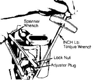
1) Remove steering gear from vehicle. See STEERING GEAR R & I under REMOVAL & INSTALLATION. Rotate gear lock-to-lock several times to drain fluid. Remove adjuster plug lock nut. See Fig. 1. Using spanner wrench, turn adjuster plug clockwise until plug is firmly seated in housing.
30539
Fig. 1: Measuring Thrust Bearing Preload Courtesy of Chrysler Corp.
2) Index mark housing opposite one hole in adjuster plug. Measure about 1/2" (13 mm) counterclockwise from mark. Mark housing.
Rotate plug counterclockwise until hole in adjuster aligns with second mark.
Tighten lock nut to 80 ft. lbs. (108 N.m). Ensure adjuster
plug remains in position. Attach INCH-lb. torque wrench to end of stub
shaft. Turn stub shaft to right stop, then back 1/4 turn.
Using torque wrench, measure rotational torque required to
turn shaft. Take reading with handle of torque wrench nearly vertical
while turning it counterclockwise at an even rate. On Cherokee and
Wrangler models, reading should be 4-10 INCH lbs. (.5-1.1 N.m). On
Grand Cherokee and Grand Wagoneer models, readings should be 6-10 INCH
lbs. (.6-1.1 N.m),
If torque reading is not within specification, adjustment
cap may not be correctly adjusted, steering gear may be assembled
incorrectly or thrust bearings and races may be defective.
SECTOR SHAFT OVER-CENTER PRELOAD
CAUTION: Always adjust worm shaft bearing preload before adjusting sector shaft over-center preload torque.
30540
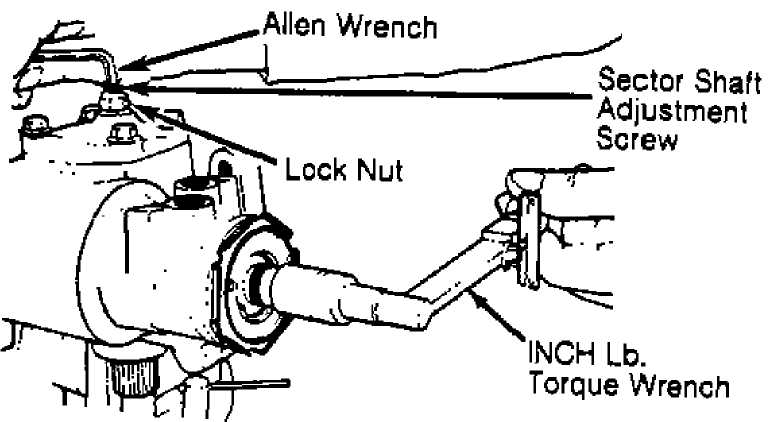
Fig. 2: Adjusting Over-Center Preload Courtesy of Chrysler Corp.
TESTING
Rotate stub shaft from stop-to-stop and count turns. To
center steering gear, rotate shaft in reverse direction 1/2 number
turned during stop-to-stop. Attach an INCH-lb. torque wrench to stub
shaft. Measure sector shaft over-center preload torque by turning
torque wrench in a 45-degree arc on each side of vertical center.
Record highest over-center rotational torque reading.
Rotational torque required to turn stub shaft should be 6-
10 INCH lbs. (.6-1.2 N.m) greater than rotational torque specified for
worm shaft. See WORM SHAFT THRUST BEARING PRELOAD.
If adjustment is necessary, loosen adjustment on sector
shaft adjuster screw until shaft has no preload. See Fig. 2. Tighten
adjuster screw until required preload is obtained. Ensure adjustment
screw does not move and tighten adjuster screw lock nut to 36 ft. lbs.
(49 N.m). Recheck preload.
HYDRAULIC SYSTEM PRESSURE TEST
With belt tension correct, disconnect power steering pump
pressure hose. Keep hose end raised to prevent fluid loss. Install
Pressure Tester (7617) between power steering pump and steering gear.
Open valve. Run engine until fluid reaches normal
operating temperature of 170F (77C). Check fluid level. Add fluid if necessary.
Note pressure reading with valve open and engine idling.
Pressure should be less than 125 psi (9 kg/cm) . If pressure exceeds
125 psi (9 kg/cm), check hoses for restrictions and poppet valve for
proper assembly.
Close and reopen the gate valve completely 3 times. Record
the highest reading each time. DO NOT close valve longer than 5
seconds. Note if pressure is within specification. Refer to the
PRESSURE TEST SPECIFICATIONS table.
If all readings are within specification and 50 psi (3.5
kg/cm) of each other, pump operation is normal.
If readings exceed specification or are not within 50
psi(3.5 kg/cm) of each other, flow control valve in pump is sticking. Remove flow control valve. Clean or replace valve as necessary.
If readings are below specification, clean or replace flow
control valve. If pressures are still low, replace pump.
If readings are all within specification, open valve and
turn steering wheel from right stop to left stop. Record pressure. DO
NOT hold wheel against stops longer than 5 seconds.
Compare both readings to pump output pressure reading
obtained. Readings should be same as pump output pressure. If readings
are low, steering gear is leaking internally. Repair or replace as
required.
PRESSURE TEST SPECIFICATIONS TABLE
Application Idle: psi (kg/cm) Relief: psi (kg/cm)
Except Wrangler .... Less Than 125 (9) 1350-1450 (95-102)
Wrangler Less Than 125 (9) 1050-1150 (74-81)
REMOVAL & INSTALLATION
POWER STEERING PUMP R & I
Removal & Installation
Loosen and remove pump drive belt. Place pan under power
steering pump. Disconnect pressure and return hoses from pump. If
equipped with remote reservoir, drain reservoir and remove supply hose
from pump. Cap ends to prevent excessive fluid loss or contamination.
Remove bracket-to-engine bolts. Remove pivot bolt. Remove
pump and mounting bracket as an assembly. To install, reverse removal
procedure. Fill and bleed system. See HYDRAULIC SYSTEM BLEEDING under
LUBRICATION.
STEERING GEAR R & I
Removal
1) Center steering gear. Disconnect intermediate shaft. Raise and support vehicle. Place drain pan under steering gear assembly. Disconnect hydraulic hoses from gear. Cap ends to prevent excessive fluid loss or contamination. Disconnect steering linkage from pitman arm.
2) Remove pitman arm from gear. Remove flexible coupling clamp bolt. Remove steering gear-to-frame bolts. Remove gear from flexible coupling and frame.
Installation
To install, reverse removal procedure. Fill pump reservoir. Bleed air from system. See HYDRAULIC SYSTEM BLEEDING under LUBRICATION.
TIE ROD END R & I
Removal & Installation
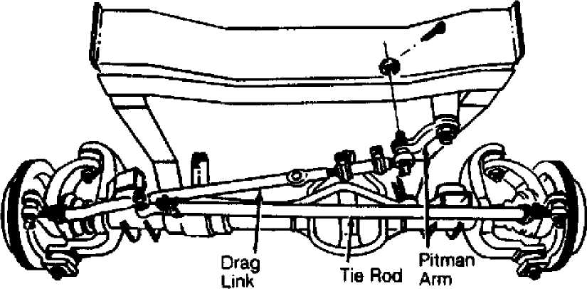
Fig. 3: Steering Linkage Component ID (Except Wrangler) Courtesy of Chrysler Corp.
Remove cotter pins and retaining nuts at tie rod end. See
Figs. 3 and 4. If necessary, disconnect steering damper from tie rod.
Using puller, separate tie rod end from steering knuckle or steering
linkage.
Loosen clamp bolts at adjusting sleeve. Remove tie rod end
from adjusting sleeve. Note number of turns required to remove tie rod
end for installation reference.
To install, reverse removal procedure. Install adjusting
sleeve clamp bolts with threaded end of bolt toward rear of vehicle
and angled slightly upward. Check and adjust toe-in. Refer to the
WHEEL ALIGNMENT SPECIFICATIONS & PROCEDURES article in WHEEL
ALIGNMENT.
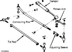
Fig. 4: Exploded View Of Steering Linkage (Wrangler) Courtesy of Chrysler Corp.
STEERING DAMPER R & I
Removal & Installation
Place front wheels in straight-ahead position. Remove cotter pins and retaining nuts and bolts at ends of damper and steering linkage. See Figs. 3 and 4. Remove damper assembly and rubber bushings. To install, reverse removal procedure.
DRAG LINK R & I
Removal & Installation
Raise and support vehicle. Separate steering damper from drag link. See Figs. 3 and 4. Remove cotter pins and nuts from both ends of drag link. Using a puller, separate drag link from steering linkage. To install, reverse removal procedure. Before installation, ensure wheels are in straight ahead position and pitman arm is centered.
OVERHAUL
STEERING GEAR OVERHAUL
Disassembly
1) Cap all openings in gear. Clean gear exterior completely. Mount gear in vise so sector shaft points downward. See Fig. 5. Rotate housing end plug retainer ring until one end of plug is over hole in housing.
14
Lock Nut
Retaining Ring
Dust Seal
Oil Seal
Needle Bearing
Adjuster Pljg
"ą×" Ring
Large Race
Thrust Bearing
Small Race
Spacer
Retainer
XT Ring
Spool Valve
Teflon Rings
Æ0" Rings
Valve Body
Stub Shaft
 "0Æ Ring
Worm Shaft
Race
22 Lower Thrust Bearing
Retainer Ring
Sector Shaft Bearing
Upper Oil Seal
Steel Washer
Lower Oil Sea)
Steel Washer
Retaining Ring
Rack Piston
Oil Seal
"0" Ring
End Plug
"O"Ring
Housing End Cover
Race
Steering Gear Housing
Lock Nut
Bolts
Side Cover
-0" Ring
29 Sector Shaft
Retainer Screws
Guide Clamp
Ball Guide
Recirculating Balls
Fig. 5: Exploded View Of Saginaw Rotary Valve Power Steering Gear Courtesy of Chrysler Corp.
2) Force end of housing end cover retaining ring from groove in housing. Remove ring. Rotate stub shaft counterclockwise to force
housing end cover from housing. Rotate stub shaft clockwise 1/2 turn to draw rack piston inward.
CAUTION: DO NOT rotate stub shaft more than necessary to remove plug as ball bearings will fall out of worm and rack piston assembly.
Remove end plug. Remove lock nut from sector shaft
adjuster. Remove side cover. Remove and discard "O" ring or gasket
from cover. Turn stub shaft until sector shaft teeth are centered in
housing.
Using a soft-faced hammer, tap end of sector shaft to free
shaft from housing. Remove sector shaft. Remove adjuster plug lock
nut. Using a spanner wrench, remove adjuster plug.
Insert Rack Piston Arbor (C-4175) into end of rack piston
assembly until arbor contacts worm shaft. Threaded arbor keeps
recirculating balls from falling out of rack piston. Turn stub shaft
counterclockwise to force rack piston onto arbor. Remove rack piston
and arbor as an assembly.
Take care to keep arbor fully inserted so recirculating
balls do not fall out. Remove stub shaft and valve body from housing.
Remove worm shaft, worm shaft lower thrust bearing and washers from
housing.
Inspection
1) Clean all internal parts in solvent, and dry with
compressed air. DO NOT steam clean hydraulic parts. Avoid wiping valve parts with cloth. Lint may cause binding of mechanism.
2) If further disassembly is required, see the following:
ADJUSTER PLUG OVERHAUL.
RACK PISTON & WORM SHAFT ASSEMBLY OVERHAUL.
VALVE BODY ASSEMBLY OVERHAUL.
HOUSING ASSEMBLY OVERHAUL.
Reassembly
1) Lubricate all parts with power steering fluid before reassembly. Install lower thrust bearing and washers on worm shaft. See Fig. 6.
NOTE: If conical thrust washers are used, ensure tapered surfaces are parallel to each other and cupped sides face toward stub shaft.
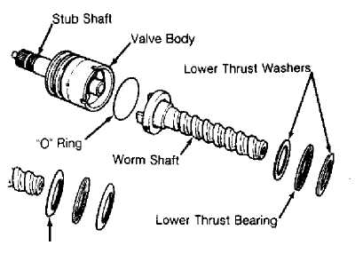 Position Conical Washers as Shown
Fig. 6: Exploded View Of Valve Body Courtesy of Chrysler Corp.
& Worm Shaft Assembly
2) Place worm shaft in valve body. Install NEW "O" ring in valve body. Align notch in valve body with pin in worm shaft. Install
valve body and worm assembly into housing. Installation is correct when fluid return port in housing is fully visible.
Place seal protector over stub shaft. Using NEW "O" ring,
install adjuster plug until it seats against valve body. Remove seal
protector from housing.
Loosely install adjuster plug lock nut. Insert rack piston
(with arbor to retain recirculating balls) into housing. Align worm
and rack piston. Turn stub shaft clockwise to engage worm. Maintain
pressure on arbor until worm is fully engaged.
Rotate stub shaft clockwise to align middle rack groove in
rack piston with center of sector shaft roller bearing. Remove arbor.
Install a NEW side cover seal or gasket.
Thread side cover onto adjuster screw until bottomed. Back
off1/2 turn. Install sector shaft so center gear tooth meshes with
center groove in rack piston. Install cover attaching bolts.
Install the adjuster lock nut halfway onto the sector
shaft. Install piston and plug in rack piston. Install housing end
cover "O" ring, end plug and retainer ring. Adjust the worm shaft
thrust bearing preload and the sector shaft over-center preload. Refer
to WORM SHAFT THRUST BEARING PRELOAD procedures under ADJUSTMENTS.
Also refer to SECTOR SHAFT OVER-CENTER PRELOAD under ADJUSTMENTS.
ADJUSTER PLUG OVERHAUL
Disassembly
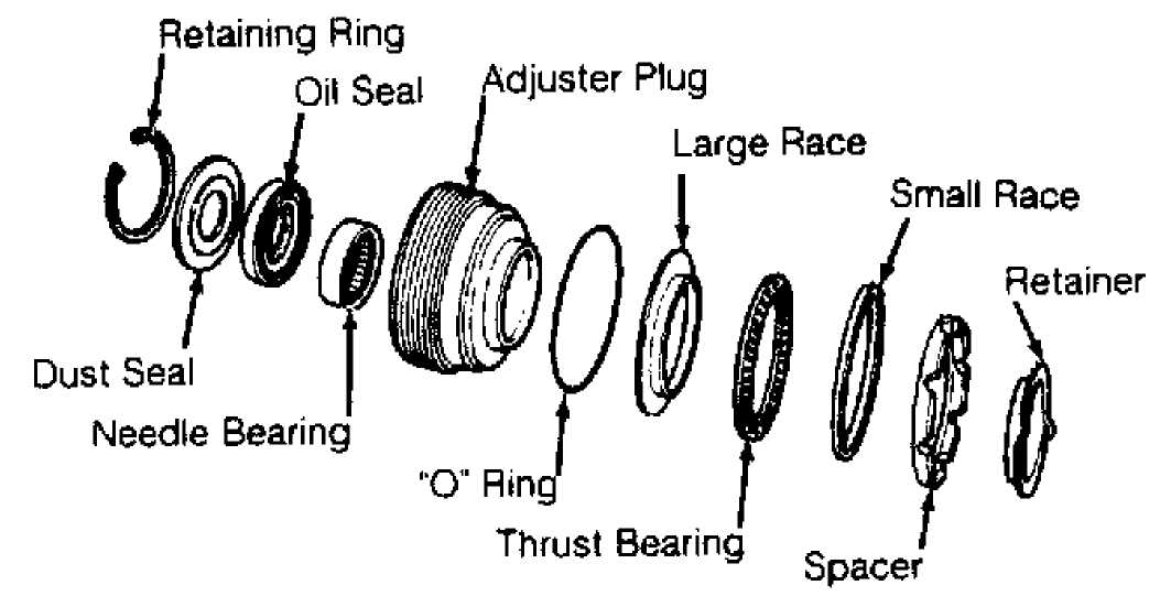
Fig. 7: Exploded View Of Adjuster Plug Assembly Courtesy of Chrysler Corp.
Inspection
Inspect thrust bearing for cracks. Check rollers for pitting,
Using a screwdriver, carefully remove and discard thrust
bearing retainer. Remove spacer, thrust bearing and bearing races. See
Fig. 7. Remove and discard adjuster plug "O" ring.
Remove retaining ring. Remove and discard dust seal. Pry
oil seal from adjuster plug, and discard seal. Inspect needle bearing.
If necessary, press bearing from spacer end of adjuster plug.
scoring and cracking. Check thrust races and spacer for damage. Replace parts as necessary.
Reassembly
Press needle bearing into adjuster plug (identification
end facing arbor) until bearing bottoms in bore. Install oil seal with
spring in seal facing adjuster plug. Install dust seal into adjuster
plug.
Rubber face of dust seal must face away from plug. Install
retaining ring and NEW adjuster plug "O" ring. Assemble thrust
bearing, thrust bearing race and spacer on adjuster plug. Flanges of
both thrust bearing races face away from plug. Install spacer. Using a
punch, tap NEW retainer into position.
RACK PISTON & WORM SHAFT ASSEMBLY OVERHAUL
Disassembly
Remove guide clamp, place complete unit on clean surface and remove ball guide. Remove arbor from rack piston. Remove and retain 24 recirculating balls. Remove Teflon piston rings and "O" ring seal.
Inspection
Clean and dry all parts. Inspect worm shaft and rack
piston grooves for scoring. Inspect recirculating balls for damage. If
any ball bearings are damaged, replace entire set. Check ball guides
for pinched ends.
Inspect lower thrust bearing races for cracks, scores and
pits. If either race is damaged, replace worm shaft and rack piston as
an assembly. Inspect rack piston teeth for chips, cracks, dents and
scores.
Reassembly
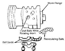
Fig. 8: Installing Recirculating Balls Into Rack Piston Courtesy of Chrysler Corp.
Lubricate NEW Teflon seal and "O" ring with power steering
fluid, and carefully install onto rack piston. Install worm shaft into
rack piston until worm shaft touches piston shoulder.
Turning worm shaft counterclockwise, insert recirculating
balls into rack piston hole nearest piston ring. See Fig. 8. Install
18 recirculating balls in ball guide, beginning with a Black ball, and
then alternating between Silver and Black. After installing each ball,
press it down to provide space for next ball. Worm shaft will spiral
outward as each ball is inserted.
Split ball guide halves, and fill one half with petroleum
jelly. Install 6 remaining recirculating balls in ball guide half
maintaining alternating pattern. Reassemble guide, and install in rack
piston. Ensure end balls in guide are alternate of end balls in rack
piston.
Install clamp, and tighten attaching bolts to 43 INCH lbs.
(4.9 N.m). Insert Rack Piston Arbor (C-4175) into rack piston until it
contacts worm shaft. Maintaining pressure on arbor, back worm shaft
completely out of rack piston. DO NOT allow recirculating balls to
drop out.
VALVE BODY ASSEMBLY OVERHAUL
Disassembly
1) Remove and discard stub shaft cap "O" ring. Lightly tap
end of stub shaft against wood block until shaft cap is free of valve
body. Pull stub shaft outward until drive pin hole is visible. See
Fig. 9.
CAUTION: DO NOT pull shaft more than 1/4" (6 mm) to access pin or spool valve may cock in valve body.
2) Disengage drive pin. Remove stub shaft from valve body and
spool valve assembly with a twisting motion. See Fig. 10. If binding
occurs, realign valve.
CAUTION: DO NOT force stub shaft or spool valve from valve body.
3) Remove spool valve from valve body with twisting motion.
Remove and discard all "O" and Teflon rings.
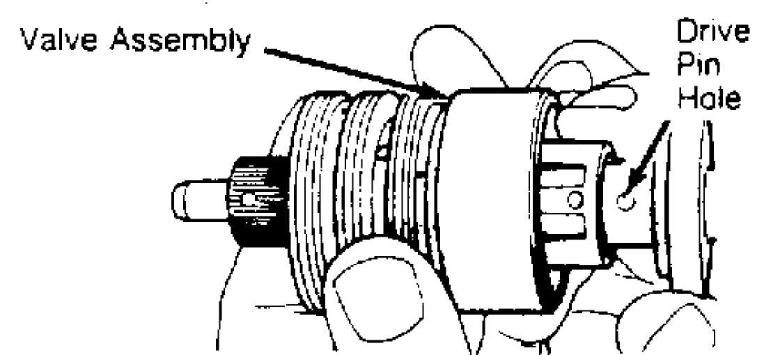
Fig. 9: Pulling Shaft From Valve Body Courtesy of Chrysler Corp.
 "0" Rmq _ ,.
^ čŹ Teflon Rings (3)
Valve Body
30334
Fig. 10: Exploded View Of Valve Body Assembly Courtesy of Chrysler Corp.
Inspection
1) Wash all parts in solvent. Dry with compressed air. Check
for evidence of leaks between stub shaft and torsion bar. Check for nicks and scores on stub shaft. If possible, smooth stub shaft using crocus cloth. Check notch in valve body skirt for wear.
NOTE: Valve body is precision-built unit with selectively fitted and balanced components. If any component is faulty, entire assembly MUST be replaced.
2) Check spool valve fit in valve body with "O" ring removed. Lubricate spool valve with power steering fluid. Rotate spool valve in valve body. If valve does not rotate freely, replace complete valve assembly.
Reassembly
Install
1) Lubricate valve body components with power steering fluid. NEW "O" rings in seal grooves. Carefully install NEW Teflon
rings over "O" rings. DO NOT damage seal rings during installation.
NOTE: Teflon seal rings may appear distorted after installation. However, heat of operation will straighten them.
Lubricate spool valve "O" ring with power steering fluid.
Install on spool valve. Carefully insert spool valve into valve body.
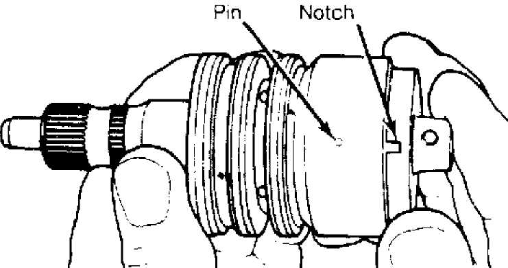
Push spool valve through valve body until drive pin hole
is visible at opposite end of valve body and spool valve is even with
notched end of valve. Install stub shaft into spool valve and valve
body. Install drive pin.
Align stub shaft drive pin with spool valve locating hole.
Align notch in stub shaft cap with pin in valve body. Press stub shaft
and spool valve into valve body. Install stub shaft cap "O" ring into
valve body. See Fig. 6.
CAUTION: Before installing valve body into gear housing, ensure
valve body stub shaft locating pin is fully engaged in stub shaft cap notch. DO NOT allow stub shaft to disengage from valve body pin. See Fig. 11.
30336
Fig. 11: Aligning Pin & Notch For Stub Shaft Courtesy of Chrysler Corp.
HOUSING ASSEMBLY OVERHAUL
Disassembly
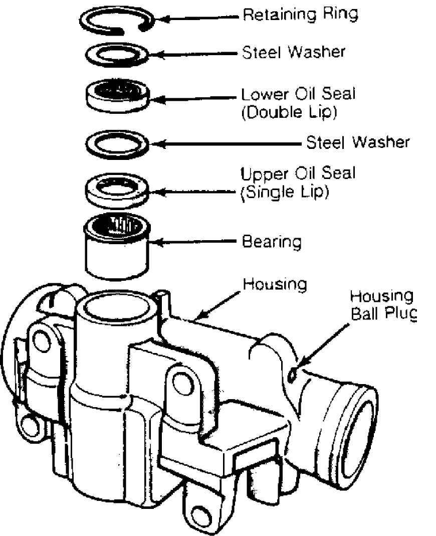
Remove sector shaft seal retaining ring. Remove steel washer. Remove lower oil seal, steel washer and upper oil seal from housing. See Fig. 12. Press sector shaft bearing out of housing from lower end.
30337
Fig. 12: Exploded View Of Gear Housing Seals & Bearing Courtesy of Chrysler Corp.
Inspection
1) If housing bore is severely worn, scored or pitted,
replace housing. Minor scratches may be removed using crocus cloth. Inspect housing ball plug for fluid leakage. Seat ball plug using
blunt punch. . _
Inspect hose connector ports in steering gear housing for
scores, cracks or damaged seats. If hose connector seat is damaged,
steering gear housing must be replaced.
Spray ball area with Loctite Solvent (7559). Dry with
compressed air. Cover ball area with Loctite Sealant (290). Allow
ssedair.CoverballareawithLoctiteSealant(290).Allowsealant to cure 2 hours. Inspect all retaining ring, bearing and seal
surfaces in housing. If any surface is worn or damaged, replace
housing.
Reassembly
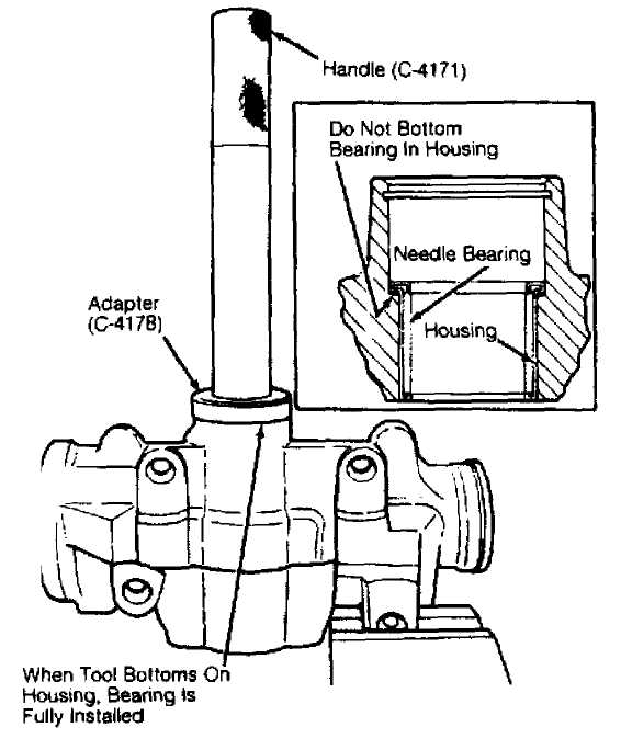
Fig. 13: Installing Sector Shaft Bearing Courtesy of Chrysler Corp.
Install sector shaft bearing in steering housxng using
Handle (8015) and Adapter (7614). See Fig. 13. Position bearing so
identification marks face away from adapter. Press in bearing until
adapter.Pressinbearinguntiladapter bottoms against housing. DO NOT bottom bearing in housing.
Install lower oil seal, steel washer and upper oil seal on
herandupperoilsealonh andleand adapter used to install bearing. See Fig. 14. Lips of both
seals should face toward housing bore. , .
Install steel washer and retaining ring in housing. Using
handle and adapter, drive in seals until retaining ring seats in
groove. Ensure hose connector seat bores are clean.
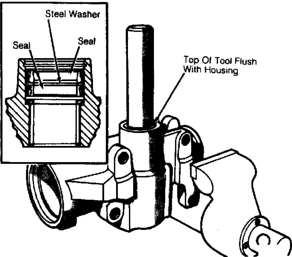
Fig. 14: Installing Sector Shaft Seals Courtesy of Chrysler Corp.
WHEEL ALIGNMENT
After performing appropriate service procedures, refer to WHEEL ALIGNMENT SPECIFICATIONS & PROCEDURES article in the WHEEL ALIGNMENT section.
TORQUE SPECIFICATIONS
CHEROKEE
TORQUE SPECIFICATIONS (CHEROKEE)
Application
Adjuster Plug Lock Nut
Ft. Lbs. (N.m)
80 (108)
Drag Link Clamp Bolt 14 (19)
Drag Link-To-Pitman Arm Nut 60 (81)
Drag Link-To-Steering Knuckle Nut 35 (47)
Pitman Arm Attaching Nut 185 (251)
Pressure & Return Hose Fitting 21 (29)
Pump Bracket-To-Engine Bolt 33 (45)
Pump Pivot Bolt 20 (27)
Pump-To-Bracket Bolt 20 (27)
Rack Piston End Plug 50 (68)
Sector Shaft Adjuster Lock Nut 36 (49)
Side Cover Bolt 45 (61)
Steering Damper-To-Axle Bracket Bolt 55 (75)
Steering Damper-To-Drag Link Nut 35 (47)
Steering Gear-To-Frame Bolt 70 (95)
Tie Rod Clamp Bolt 22 (30)
Tie Rod End Stud Nut 35 (47)
GRAND CHEROKEE & GRAND WAGONEER
TORQUE SPECIFICATIONS (GRAND CHEROKEE & GRAND WAGONEER)
Application Ft. Lbs. (N.m)
Adjuster Plug Lock Nut 80 (108)
Drag Link Clamp Bolt 30 (41)
Drag Link-To-Pitman Arm Nut 60 (81)
Pitman Arm Attaching Nut 185 (251)
Pressure & Return Hose Fitting 21 (29)
Pump Bracket-To-Engine Bolt 30 (41)
Pump Pivot Bolt 20 (27)
Pump-To-Bracket Bolt 20 (27)
Rack Piston End Plug 75 (102)
Sector Shaft Adjuster Lock Nut 36 (49)
Side Cover Bolt 45 (61)
Steering Damper-To-Axle Bracket Bolt 55 (75)
Steering Damper-To-Drag Link Nut 35 (47)
Steering Gear-To-Frame Bolt (1) 65 (88)
Tie Rod Clamp Bolt 22 (30)
Tie Rod End Stud Nut 35 (47)
(1) - This specification has been revised as per TSB # 19-02-93 dated Feb. 22, 1993.
WRANGLER
TORQUE SPECIFICATIONS (WRANGLER)
Application Ft. Lbs. (N.m)
Adjuster Plug Lock Nut 80 (108)
Drag Link Clamp Bolt 36 (49)
Drag Link-To-Pitman Arm Nut 60 (81)
Drag Link-To-Tie Rod Nut 35 (47)
Pitman Arm Attaching Nut 185 (251)
Pressure & Return Hose Fitting 21 (29)
Pump Bracket-To-Engine Bolt 33 (45)
Pump Pivot Bolt 20 (27)
Pump-To-Bracket Bolt 20 (27)
Rack Piston End Plug 50 (68)
Sector Shaft Adjuster Lock Nut 36 (49)
Side Cover Bolt 45 (61)
Steering Damper-To-Axle Bracket Bolt 55 (75)
Steering Damper-To-Drag Link Nut 35 (47)
Steering Damper-To-Tie Rod Nut 53 (72)
Steering Gear-To-Frame Bolt 75 (102)
Tie Rod Clamp Bolt 25 (34)
Tie Rod End Stud Nut 35 (47)