Ā
1993 Jeep Cherokee
1993 SUSPENSION Chrysler Corp. Front
Jeep; Cherokee, Grand Cherokee, Grand Wagoneer, Wrangler
DESCRIPTION
On all models except Wrangler, front suspensions consist of axle, 2 coil springs, track bar, stabilizer bar and upper and lower control arms. Track bar is used to minimize front axle side-to-side movement. Stabilizer bar and shock absorbers control suspension spring movement.
Wrangler models use leaf spring front suspension with shock absorbers, stabilizer bar and a track bar.
ADJUSTMENTS & INSPECTION
WHEEL ALIGNMENT SPECIFICATIONS & PROCEDURES
NOTE: See SPECIFICATIONS & PROCEDURES article in WHEEL ALIGNMENT.
WHEEL BEARING
NOTE: Wheel bearings on all 4WD models are nonadjustable. If wheel bearings require service, see WHEEL BEARINGS under REMOVAL & INSTALLATION.
2WD
Raise and support vehicle. Turn wheel by hand while
placing fingers of free hand on rotor shield. If any roughness is
detected proceed to WHEEL BEARINGS under REMOVAL & INSTALLATION.
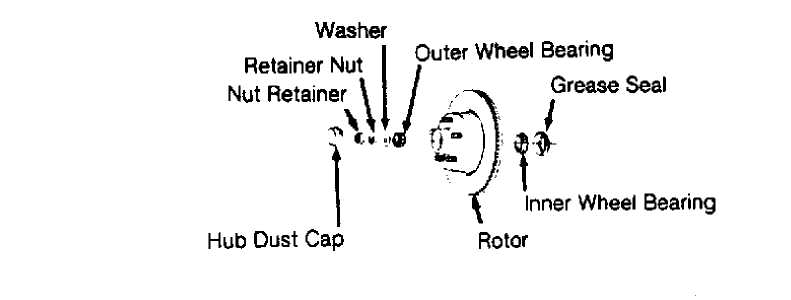
Remove wheel and tire assembly. See Fig. 1.
Remove hub dust cap, cotter pin and nut retainer. Ensure
bearings are thoroughly packed with lithium grease. Rotate hub and
rotor assembly by hand, tighten retainer nut to 21 ft. lbs. (29 N.m)
to seat bearings.
Loosen retainer nut 1/2 turn while rotating hub. Then
retighten nut to 19 INCH lbs. (2 N.m). Install nut retainer and new
cotter pin. Clean hub dust cap and coat inside with clean grease.
Reverse removal procedure for remaining components.
2W0 MODELS
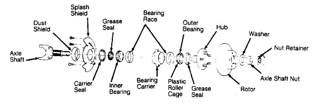
Fig. 1: 2WD Hub/Rotor Assy. Courtesy of Chrysler Corp.
4WD MODELS
4WD Hub/Bearing Carrier Assy.
REMOVAL & INSTALLATION
WHEEL BEARINGS
Removal (2WD)
Raise and support vehicle. Remove wheel assembly. Remove
brake caliper and suspend caliper with wire. DO NOT allow caliper to
hang on brake hose.
Remove hub dust cap, cotter pin, nut retainer, nut, washer
and outer wheel bearing. Remove rotor and hub assembly. Pry grease
seal from hub. Remove inner wheel bearing.
WARNING: DO NOT allow bearings to spin freely when drying with
compressed air. Damage to bearings or serious injury could occur.
Inspection
Clean bearings and hub in solvent and dry with compressed air. Inspect bearings and races for damage or excessive wear.
Installation (2WD)
To install, reverse removal procedure. Pack bearings with wheel bearing grease. Adjust wheel bearings. See WHEEL BEARING under
ADJUSTMENTS & INSPECTION.
NOTE: On 4WD models, front wheel bearings cannot be serviced
separately. If defective, hub and bearing must be replaced as an assembly. See HUB & BEARING under REMOVAL & INSTALLATION in FRONT AXLES article in DRIVE AXLES.
SHOCK ABSORBER
Removal & Installation
With vehicle at normal ride height, remove nut, washer and rubber grommet from top of shock absorber. Raise and support vehicle. Remove lower shock mounting bolts from axle housing bracket. Remove shock absorber. Inspect units for damage or leakage. To install, reverse removal procedure.
STEERING KNUCKLE
Removal
1) Raise and support vehicle. Remove wheel, disc brake
caliper, rotor, cotter pin, nut retainer, and axle hub nut. Remove
hub-to-steering knuckle attaching bolts. Remove hub and rotor shield
from steering knuckle. Remove axle shaft from axle tube. See FRONT
AXLES article in DRIVE AXLES.
NOTE: DO NOT disconnect caliper unless service is needed. Support caliper with wire to prevent hose damage.
2) On models with front axle shift motor, remove outer axle
shaft from right axle tube. Leave shift collar on intermediate shaft.
On all models, remove caliper anchor plate from steering knuckle.
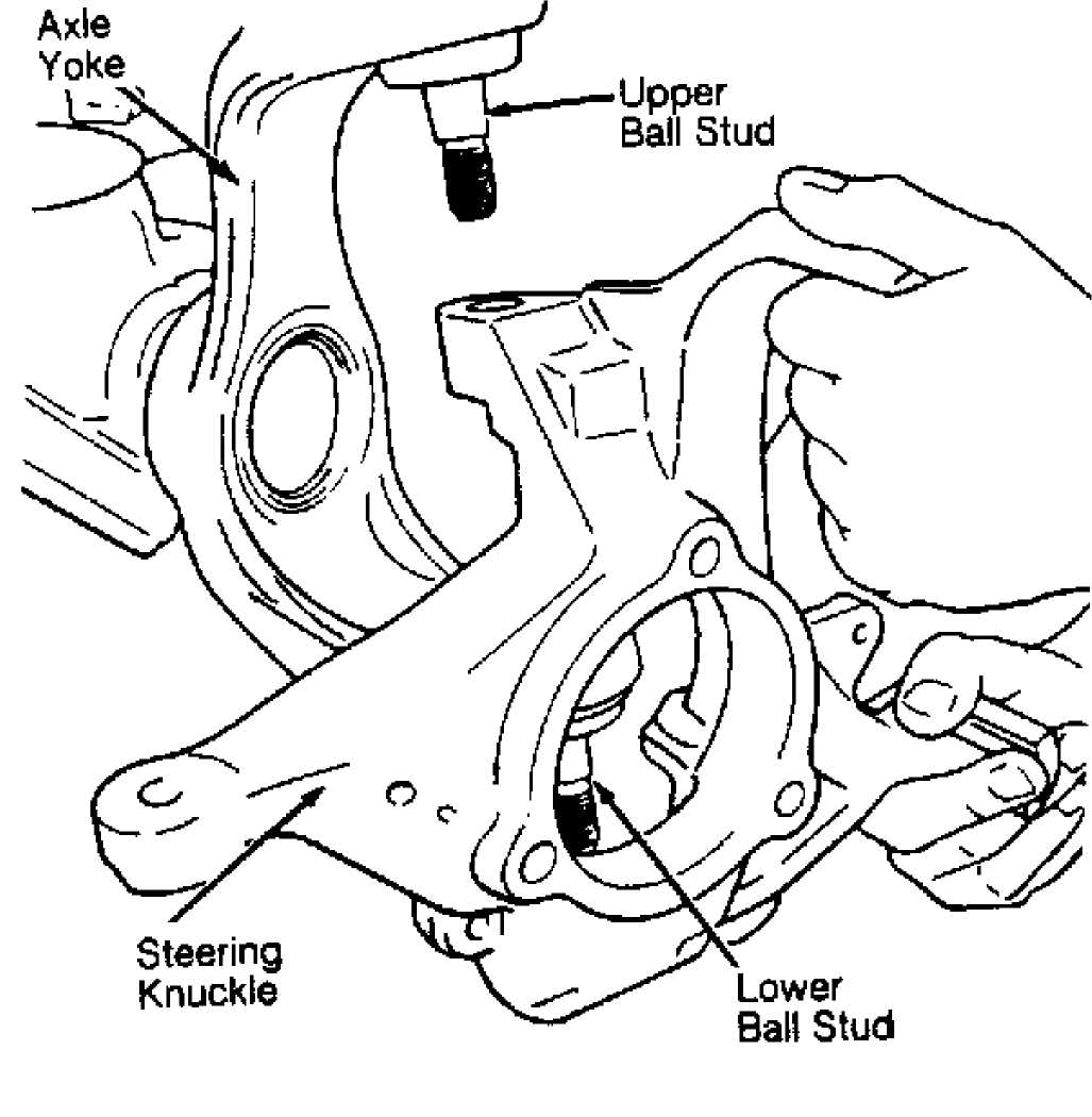
Remove steering knuckle and ball joint cotter pins. Remove ball joint
nuts. Strike steering knuckle at ball joint stud boss with a brass
hammer to loosen knuckle from ball joint studs. Remove steering
knuckle. See Fig. 2.
Installation
1) Position steering knuckle over ball joint studs and
install nuts. Tighten nuts to specification. Install NEW cotter pins. Install caliper anchor plate and tighten bolts to specification. See TORQUE SPECIFICATIONS TABLE at the end of this article. Install axle shafts into axle tubes.
On vehicles with front axle shift motor, ensure shift
collar is correctly positioned on intermediate axle shaft, install
axle into shift collar inside axle tube. Ensure axle shaft is
completely engaged with shift collar.
On all models, apply bearing grease to spindle hub bore in
steering knuckle and install rotor shield and hub. Tighten spindle hub
bolts. Install hub washer and nut. Tighten hub nut to specification.
Install hub nut retainer and install NEW cotter pin. Install rotor,
caliper and wheel. Lower vehicle.
92G21838
Fig. 2: Removing & Installing Steering Knuckle Assembly Courtesy of Chrysler Corp.
ANTI-LOCK BRAKE WHEEL SPEED SENSOR
Removal & Installation (Cherokee 4WD, Grand Cherokee &
Grand Wagoneer)
1) Raise and support front of vehicle. Note sensor wire routing for installation reference. Clean area around sensor to prevent damage during removal. Remove wheel speed sensor from steering knuckle. Unseat sensor wire retaining grommet.
2) Inside engine compartment, unplug sensor connector from anti-lock harness connector. Remove sensor. To install, reverse removal procedure. See Fig. 3.
NOTE:
Air gap between ABS wheel speed sensor and tone wheel is not adjustable.
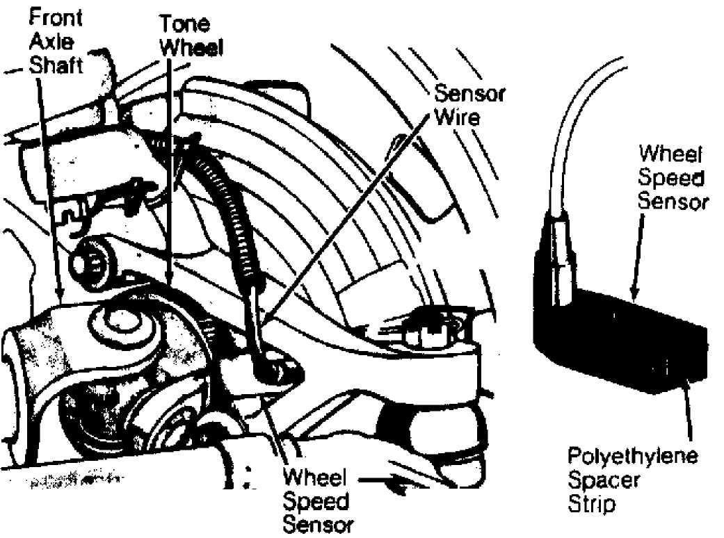
Fig. 3: Locating Anti-Lock Brake Wheel Speed Sensor Courtesy of Chrysler Corp.
UPPER & LOWER BALL JOINTS
Removal
1) Remove steering knuckle assembly. See STEERING KNUCKLE. To remove upper ball joint, install Receiver (J-34503-1) over top of upper ball joint. Place Adapter (J-34503-3) in "C" clamp. Install "C" clamp, adapter and receiver. Tighten "C" clamp screw to remove ball joint. See Fig. 4.
UPPER BALL JOINT
 REMOVAL INSTALLATION
 LOWER BALL JOINT
30213
Fig. 4: Removing & Installing Ball Joint Courtesy of Chrysler Corp.
2) To remove lower ball joint, position Receiver (J-34503-1) onto "C" clamp and Adapter (J-34503-3) at base of clamp. See Fig. 4.Install "C" clamp, adapter and receiver. Tighten "C" clamp to remove ball joint. See Fig. 4.
Installation
Place upper ball joint in position. Position Ball Joint
Installer (J-34503-5) over new upper ball joint. Install Receiver (J-
34503-12) and "C" clamp. Tighten "C" clamp and fully seat ball joint.
See Fig. 4.
To install lower ball joint, position Ball Joint Installer
(J-34503-4), "C" clamp and Receiver (J-34503-12). See Fig. 4. Tighten
"C" clamp to install ball joint. Ensure ball joint is fully seated.
Install steering knuckle. See TORQUE SPECIFICATIONS TABLE at the end
of this article.
COIL SPRING
Removal & Installation
Raise and support vehicle on frame rails. Remove wheel
assembly. On 4WD models, Place reference mark on drive shaft and front
axle flanges. Disconnect drive shaft at front axle.
Place jack stand under axle housing. Disconnect lower
control arms at axle housing. Disconnect stabilizer bar links and
lower shock absorber mounting bolts at axle housing. Disconnect track
bar at frame rail bracket. Disconnect tie rod from pitman arm.
Lower axle housing to relieve spring pressure. Remove
spring retainer mounting bolt. Remove spring retainer and coil spring.
Note component location for reassembly reference. To install, reverse
removal procedure.
LEAF SPRING
Removal & Installation
Raise and support vehicle. Raise axle assembly with jack
to relieve spring tension. Remove wheels and loosen stabilizer bar
link nut.
Remove spring "U" bolts and plate. Remove spring-to-front
shackle bolt and spring-to-rear frame hanger bolt. Remove spring. To
install, reverse removal procedure. Ensure spring center bolt is
seated in axle housing. Tighten spring-to-front shackle bolt and
spring-to-rear frame hanger bolt with vehicle at normal operating
height. See TORQUE SPECIFICATIONS TABLE at the end of this article.
UPPER CONTROL ARM & AXLE HOUSING PIVOT BUSHING
Removal & Installation
Raise vehicle and remove upper control arm mounting bolt
from axle housing. Disconnect control arm mounting bolt at frame rail.
Remove upper control arm.
Inspect control arm for damage or distortion and replace
as needed. Check pivot bushings for excessive distortion,
deterioration or wear.
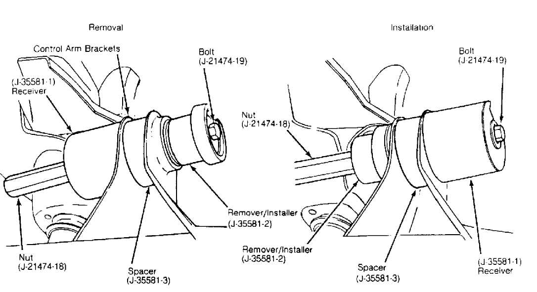
If pivot bushing requires replacement, on 2WD models,
install Spacer (J-33581-3) between ears of control arm bracket on axle
housing. See Fig. 5.
NOTE: Spacer (J-33581-3) is not used on 4WD models, as solid control arm brackets are used. DO NOT attempt to remove upper control arm pivot bushing on 2WD models without spacer. Axle bracket will be distorted if spacer is not used.
30214
Fig. 5: Removing & Installing Upper Control Arm Bushing Courtesy of Chrysler Corp.
Install Bushing Remover/Installer Set (J-35581, which
includes Spacer J-35581-3, Remover/Installer J-35581-2, Receiver J-
35581-1, Bolt J-21474-19 and Nut J-21474-18) onto pivot bushing. See
Fig. 5.
Rotate nut to press bushing from axle housing and into
receiver. See Fig. 5. Once bushing is removed, remove bushing
remover/installer components.
CAUTION: On 2WD models, spacer must remain installed for bushing installation.
6) Position bushing on Remover/Installer (J-35581-2) and Nut
(J-21474-18). Position bushing and installer components in control arm
bracket. Assemble remaining installer components. See Fig. 5.
7) Rotate nut to press bushing into housing until fully
seated in bore. See Fig. 5. Remove bushing installer components. To
install upper control arm, reverse removal procedure.
LOWER CONTROL ARM
Removal & Installation
Raise and support vehicle. Support axle. Disconnect lower control arm mounting bolts at axle housing and frame brackets. Remove lower control arm. To install, reverse removal procedure.
TRACK BAR
Removal & Installation
Raise and support vehicle. Remove cotter pin (if used) and
nut at frame rail bracket. Remove track bar-to-axle housing bracket.
On all models except Wrangler, track bar is fastened to
frame bracket with a tapered rod end, similar to a tie rod. Use of a
puller may be necessary to free track bar from bracket. Remove track
bar. To install, reverse removal procedure. FRONT STABILIZER BAR
Removal & Installation
Raise and support vehicle. Disconnect stabilizer bar from
stabilizer bar links. Remove stabilizer bar bracket-to-frame bolts.
Remove brackets. Remove stabilizer bar and bushings.
To install, lubricate stabilizer bar bushings and grommets
with rubber lubricant. Install stabilizer bar link brackets on axle
(if removed). Tighten to specification. Install stabilizer bar and brackets on the frame. DO NOT tighten bolts at this time.
3) Install stabilizer bar-to-link bolts. Tighten stabilizer
bracket-to-frame bolts to specification and then tighten stabilizer
bar link bolts. See TORQUE SPECIFICATIONS TABLE at the end of this
article.
TORQUE SPECIFICATIONS
TORQUE SPECIFICATIONS TABLE
Application
Ft. Lbs. (N.m)
Except Wrangler
Axle Shaft Nut 175 (237)
Ball Joint Nut 75 (102)
Bearing Assembly-To-Steering Knuckle Bolt 75 (102)
Brake Caliper
Anchor Bolt 77 (104)
Mounting Pin 30 (41)
Control Arm Bolt Upper
At Axle 55 (75)
At Frame 66 (89)
Lower 133 (180)
Shock Absorber Nut (Lower) 14 (19)
Stabilizer Bar
Frame Bolt 55 (75)
Link Bolt 27 (37)
Stabilizer Bar Link-To-Bracket Bolt 70 (95)
Tie Rod-To-Steering Knuckle Nut 35 (47)
Track Bar
Frame Rail Bracket Nut 63 (85)
Axle Mount Bolt 74 (100)
Wheel Bearing Outer Lock Nut 50 (68)
Wheel Lug Nut 88-110 (119-149)
Wheel Speed Sensor Bolt 11 (15)
Wrangler
Axle Shaft Nut 175 (237)
Ball Joint Nut 75 (102)
Bearing Assembly-To-Steering Knuckle Bolt 75 (102)
Brake Caliper
Anchor Bolt 77 (104)
Mounting Pin 30 (41)
Shock Absorber
Lower Bolt 45 (61)
Upper Stud Nut 10 (14)
Spring-To-Frame Bracket Bolt 105 (142)
Spring-To-Front Shackle Bolt 95 (129)
Spring "U" Bolt Nut 90 (122)
Stabilizer Bar
Link Bolt 45 (61)
Mounting Bracket Bolt 55 (75)
Stabilizer Bar Link-To-Spring Bracket Nut 45 (61)
Tie Rod-To-Steering Knuckle Nut 35 (47)
Track Bar Bolt 74 (100)
Wheel Bearing Outer Lock Nut 50 (68)
Wheel Lug Nut 88-110 (119-149)
INCH Lbs. (N.m)
Axle Shift Motor Bolt 101 (11)
Shock Absorber Nut (Upper) 96 (10)