1993 Jeep Cherokee
1993 ACCESSORIES & EQUIPMENT Chrysler Corp. Rear Window Defoggers
Jeep; Cherokee, Grand Cherokee, Grand Wagoneer, Wrangler
DESCRIPTION & OPERATION
System consists of 2 vertical bus bars and horizontal rows of heating elements fused to inside of rear glass. On Cherokee, power circuit to grid is protected by fuse No. 18 (25-amp) located in fuse box. Power for relay is protected by fuse No. 8 (20-amp) located in fuse box.
On Grand Cherokee and Grand Wagoneer, power circuit to grid is protected by circuit breaker No. 28 (30-amp) located in fuse box. Power for relay is protected by fuse No. 19 (15-amp) located in fuse box. Fuse No. 23, located in fuse box, controls power to switch light and side mirrors.
On Wrangler, power circuit to grid is protected by fuse No. 6 (25-amp) located in fuse box. Power for relay is protected by fuse No. 9 (15-amp) located in fuse box.
TESTING
NOTE: For terminal identification, see appropriate chassis wiring in WIRING DIAGRAMS.
SYSTEM TESTING
On Wrangler, check fuses No. 6 and 9. On Cherokee, check
HTD/WDW and TURN fuses. On Grand Cherokee and Grand Wagoneer, check
fuses No. 19 and 23 and circuit breaker No. 28. Replace as necessary.
If fuses are okay, check for voltage on battery side of
fuse No. 6 (Wrangler), HTD/WDW fuse (Cherokee) or fuse No. 28 (Grand
Cherokee and Grand Wagoneer). If battery voltage is not present,
replace maxi-fuse in Power Distribution Center (PDC) located near
coolant reservoir (Cherokee) or near battery (Wrangler, Grand Cherokee
and Grand Wagoneer).
If battery voltage is present, check ignition side of fuse
No. 9 (Wrangler), TURN fuse (Cherokee) or fuse No. 19 (Grand Cherokee
and Grand Wagoneer) for voltage. If battery voltage is not present,
check for an open circuit from ignition switch.
DEFOGGER SWITCH TEST
Cherokee & Wrangler
Disconnect defogger switch connector. Turn ignition switch
to RUN position. Measure voltage at defogger switch connector terminal
"D". About 5 volts should be present. If about 5 volts are not
present, repair open circuit from relay.
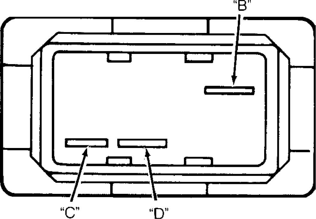
Measure resistance across switch terminals "B" and "D".
See Figs. 1 and 2. With switch button depressed, approximately zero
ohms should be present. Measure resistance across switch terminals "D"
and "C". With switch button depressed, zero ohms should be present.
Measure resistance across switch terminals "B" and "C". Approximately
zero ohms should be present.
Grand Cherokee And Grand Wagoneer
1) Disconnect defogger switch connector. Using a jumper wire,
apply 12 volts to switch terminal No. 1. Using another jumper wire, connect terminal No. 3 of switch to ground. If switch indicator lights, go to next step. If indicator does not light, replace switch.
2) Remove jumper wires. Connect an ohmmeter between switch terminals No. 2 and 3. Depress switch. Ohmmeter should indicate 10 ohms. If ohmmeter does not indicate 10 ohms, replace switch. If ohmmeter indicates 10 ohms, check for an open circuit between terminal No. 1 and fuse No. 23, between terminal No. 3 and ground and between relay terminals No. 2 and 3.
92A22327
Fig. 1: Defogger Switch Terminal ID (Cherokee & Wrangler) Courtesy of Chrysler Motors.
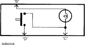
Fig. 2: Defogger Switch Internal Component ID (Cherokee & Wrangler) Courtesy of Chrysler Motors.
DEFOGGER RELAY TEST
1) Disconnect defogger relay connector. Turn ignition switch
to RUN position. Measure voltage at relay connector terminal No. 4
(Cherokee and Wrangler) or No. 5 (Grand Cherokee and Grand Wagoneer). Battery voltage should be present. If battery voltage is not present, repair open circuit to fuse No. 9 (Wrangler), fuse No. 19 (Grand Cherokee and Grand Wagoneer) or HTD/WDW fuse (Cherokee).
Measure voltage at relay connector terminal No. 4. Battery
voltage should be present. If battery voltage is not present, repair
open circuit from fuse No. 6 (Wrangler), TURN fuse (Cherokee) or
circuit breaker No. 28 (Grand Cherokee and Grand Wagoneer).
Turn ignition switch to OFF position. Check resistance
between relay connector terminal No. 1 and left (driverÆs side) of
defogger grid. Zero ohms should be present. If zero ohms are not
present, repair open circuit between relay connector and left side of
defogger grid.
Measure resistance between relay connector terminal No. 2
and ground. Zero ohms should be present. If zero ohms are not present,
repair open circuit between relay connector and ground.
Reconnect relay connector. Turn ignition switch to RUN
position. Measure voltage at terminal No. 3. About 5 volts should be
present. If about 5 volts are not present, replace defogger relay.
GRID POWER & GROUND TEST
Turn defogger on. Turn ignition switch to RUN position.
Measure voltage at left (driver side) of defogger grid. Battery
voltage should be present. If battery voltage is not present, repair
open circuit from defogger relay.
Turn ignition switch to OFF position. Measure resistance
from right side of defogger grid to ground. Zero ohms should be
present. If zero ohms are not present, repair open circuit between
right side of defogger grid and ground.
LOCATING GRID FILAMENT BREAK
With engine running, turn defogger switch on. Defogger
light should illuminate. On inside glass surface, connect voltmeter
positive lead to power feed side vertical grid element and the
negative voltmeter lead to ground side of vertical grid element.
Voltmeter should read 11-13 volts. Connect voltmeter
negative lead to a good ground. Voltmeter reading should remain
constant. Using voltmeter positive lead, contact each grid at grid
centerline.
Voltage reading should be approximately half the previous
reading (about 6 volts). A reading of zero volts indicates a break in
the grid between positive voltmeter lead (centerline) and ground. A
reading of 12 volts indicates a break in the grid between power feed
side and centerline (or positive voltmeter lead).
To pinpoint break, move voltmeter positive lead left or
right along grid until a sudden change in voltmeter reading occurs.
That indicates the exact location of grid filament break.
ON VEHICLE SERVICING
GRID FILAMENT REPAIR
Mark location of broken or open grid on exterior surface
of glass using a marking pen. Using fine steel wool, lightly rub area
to be repaired inside rear window. Clean area using alcohol.
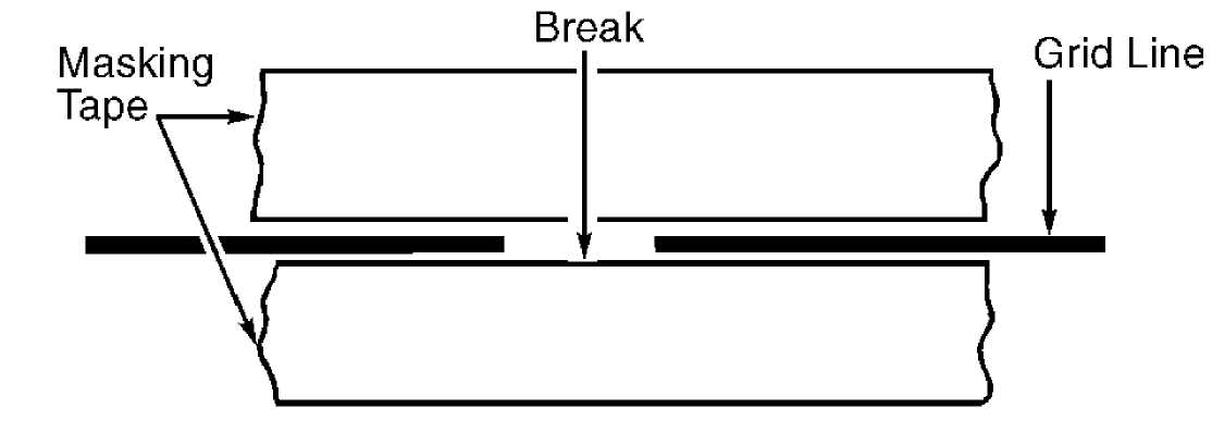
Place 2 strips of masking tape to inside surface of rear
window, above and below break in grid. See Fig. 3. Thoroughly mix
conductive epoxy. Apply epoxy on grid break, overlapping both ends of
break.
3) Carefully remove masking tape from grid line. Allow epoxy to cure 24 hours at room temperature or use a heat gun for 15 minutes. Hold gun about 10" from damaged area.
G92A01033
Fig. 3: Repairing Defogger Grid Courtesy of Chrysler Motors.
REMOVAL & INSTALLATION
DEFOGGER SWITCH
Removal & Installation (Cherokee)
Disconnect negative battery cable. Remove instrument panel bezel. Remove switch housing panel. Disconnect switch connector. Depress switch mounting tabs, and remove switch. To install, reverse removal procedure.
Removal & Installation (Grand Cherokee And Grand Wagoneer)
Disconnect negative battery cable. Remove ash tray. Remove
6 screws retaining center cluster bezel. Remove center bezel. Remove 2
screws holding dash pad located behind top of center bezel.
Pry defroster grille out of dash pad. Unplug sensors and
set defroster grille aside. Remove 4 screws in defroster duct opening
holding dash pad. Remove 3 screws above instrument panel cluster
holding dash pad.
Open glove box, and remove 2 screws holding dash pad.
Remove dash pad by pulling upward and unsnapping end clips. With
driverÆs door open, remove one screw from side of lower trim panel.
Remove one screw from bottom of lower trim panel and pull panel off.
Ensure clip holding lower trim panel to instrument panel is
disengaged.
Remove 4 screws holding steering column cover. Remove 3
screws holding bottom of bezels. Remove 2 screws holding top of end
bezel and switch pod bezel. Remove end bezel. Remove 2 screws holding
left side of switch pod bezel. Remove 3 screws holding right side of
switch pod bezel.
Pull switch pod bezel out far enough to remove switch
connectors. Disconnect connectors from each switch pod and remove
bezel. Remove switch screws and switch. To install, reverse removal
procedure.
Removal & Installation (Wrangler)
Disconnect negative battery cable. Remove 6 instrument panel shroud screws. Slide shroud toward steering wheel. Remove 3 defogger switch bezel screws. Disconnect defogger switch connector. Squeeze ends of switch to release plastic retaining fingers. To install, reverse removal procedure.
DEFOGGER RELAY
Removal & Installation (Cherokee & Wrangler)
Rear defogger relay is Red and located behind instrument
panel, to right of steering column. Remove lower instrument panel trim
panel. Remove relay from connector.
Removal & Installation (Grand Cherokee And Grand Wagoneer) Rear defogger relay is Red and located in relay center, in glove box. Remove relay center cover. Remove relay from connector.
WIRING DIAGRAMS
See appropriate chassis wiring diagram in WIRING DIAGRAMS.