F - BASIC TESTING - 2.5L & 4.0L
1993 Jeep Cherokee
1993 ENGINE PERFORMANCE
Chrysler Corp. 2 . 5L & 4.0L Basic Diagnostic Procedures
Jeep; Cherokee, Grand Cherokee, Wrangler
INTRODUCTION
The following diagnostic steps will help prevent overlooking a simple problem. This is also where to begin diagnosis for a no-start condition.
The first step in diagnosing any driveability problem is verifying the customerÆs complaint with a test drive under the conditions the problem reportedly occurred.
Before entering self-diagnostics, perform a careful and complete visual inspection. Most engine control problems result from mechanical breakdowns, poor electrical connections or damaged/misrouted vacuum hoses. Before condemning the computerized system, perform each test listed in this article.
NOTE: Unless stated otherwise in test procedure, perform all
voltage tests with a Digital Volt-Ohmmeter (DVOM) having a minimum 10-megohm input impedance.
PRELIMINARY INSPECTION & ADJUSTMENTS
VISUAL INSPECTION
Visually inspect all electrical wiring, looking for chafed, stretched, cut or pinched wiring. Ensure electrical connectors fit tightly and are not corroded. Ensure vacuum hoses are properly routed and are not pinched or cut. See M - VACUUM DIAGRAMS article in the ENGINE PERFORMANCE Section to verify routing and connections. Inspect air induction system for possible vacuum leaks.
MECHANICAL INSPECTION
Compression
Check engine mechanical condition with a compression gauge, vacuum gauge or engine analyzer. See engine analyzer manual for specific instructions.
WARNING: DO NOT use ignition switch during compression tests on fuel injected vehicles. Crank engine with a remote starter. Fuel injectors on many models are triggered by ignition switch during cranking mode, which can create a fire hazard or contaminate the engineÆs oiling system.
COMPRESSION RATIO TABLE
Application Specification
2.5L 9.1:1
4.0L 8.8:1
5.2L 9.1:1
NOTE: Compression pressure and cylinder pressure variation are not available from manufacturer.
Exhaust System Backpressure
The exhaust system can be checked with a vacuum or pressure gauge. Remove O2 sensor. Connect a 0-5 psi pressure gauge and run engine at 2500 RPM. If exhaust system backpressure is greater than 1 3/4 - 2 psi, exhaust system or catalytic converter is plugged.
If a vacuum gauge is used, connect vacuum gauge hose to intake manifold vacuum port and start engine. Observe vacuum gauge. Open throttle part way and hold steady. If vacuum gauge reading slowly drops after stabilizing, check exhaust system for restriction.
FUEL SYSTEM
FUEL PRESSURE
Basic diagnosis of fuel system should begin with determining fuel system pressure.
WARNING: ALWAYS relieve fuel pressure before disconnecting any fuel injection-related component. DO NOT allow fuel to contact engine or electrical components.
Fuel System Pressure Release
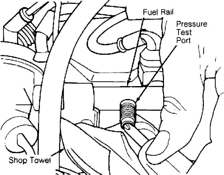
Fig. 1: Releasing Fuel System Pressure Courtesy of Chrysler Corp.
Deadhead Pressure
1) Relieve fuel system pressure. See FUEL SYSTEM PRESSURE
Disconnect negative battery cable. Remove fuel filler cap. Remove cap from pressure test port on fuel rail. Position shop towels to soak up any spilled fuel. Using a small screwdriver or pin punch, push test port valve in to relieve fuel pressure. See Fig. 1. Install cap over test port. Reconnect negative battery cable.
RELEASE. Connect a 0-60 psi (0-4.2 kg/cm) fuel pressure gauge to the pressure test port fitting on fuel rail.
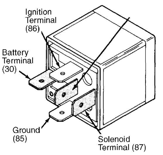
Remove fuel pump relay (located in power distribution
center). Using a jumper wire, connect terminals No. 30 and 87. See
Fig. 2. Note fuel pressure gauge reading, and momentarily pinch off
fuel return line.
Fuel pressure should be at least 53 psi (3.7 kg/cm) . DO
NOT allow pressure to exceed 60 psi (4.2 kg/cm) . Release fuel return
line.
Fuel System Pressure Test
Relieve fuel system pressure. See FUEL SYSTEM PRESSURE
RELEASE. Connect a 0-60 psi (0-4.2 kg/cm) fuel pressure gauge to the
pressure test port fitting on fuel rail.
Remove vacuum line from fuel pressure regulator. Start
vehicle and note gauge reading. Reconnect vacuum line and note gauge
reading. See FUEL SYSTEM PRESSURE SPECIFICATIONS table. Ensure
pressure readings are as specified. If fuel pressure is not higher
with vacuum line disconnected, inspect pressure regulator vacuum line
for cause of no vacuum.
If fuel pressure is high, inspect fuel return line for
kinks and blockage. If fuel pressure is low, momentarily pinch off
fuel return line. If pressure remains low, inspect fuel supply line,
fuel filter and fuel rail inlet for blockage. If pressure rises,
replace fuel pressure regulator.
FUEL SYSTEM PRESSURE SPECIFICATIONS TABLE
Application psi (kg/cm2)
Vacuum Line Disconnected 39 (2.7)
Vacuum Line Connected 31 (2.2)
Fuel System Rest Pressure
Relieve fuel system pressure. See FUEL SYSTEM PRESSURE
RELEASE. Connect a 0-60 psi (0-4.2 kg/cm) fuel pressure gauge to the
pressure test port fitting on fuel rail. Start engine and note reading
on pressure gauge. Shut engine off.
Wait 30 minutes and check fuel pressure. Fuel pressure
should be within 20 psi (1.4 kg/cm) of first reading. If pressure is
not as indicated, check fuel system for leaks at fuel pressure
regulator, fuel pump check valve or fuel injectors.
Capacity (Volume) Test
Relieve fuel system pressure. See FUEL SYSTEM PRESSURE
RELEASE. Disconnect fuel line on fuel rail. Place fuel line into a
graduated container.
Remove fuel pump relay (located in power distribution
center). Using a jumper wire, connect terminals No. 30 and 87. See
Fig. 2. Volume of fuel should be 1.05 qts. (1.0L) in one minute. If
fuel volume is not as specified, check for a plugged fuel filter or
fuel pump inlet sock.
Fuel Pump Relay
Disconnect negative battery cable. Remove Powertrain
Control Module (PCM) harness connector. Reconnect battery cable. Turn
ignition on. Check for voltage at Dark Blue/Yellow wire on Cherokee
and Wrangler or Pink wire on Grand Cherokee in PCM harness connector.
If voltage is not present, go to step 4). If voltage is present,
ground the wire. Fuel pump should work.
If fuel pump does not work, check if relay clicks. If
relay does not click, go to step 5). If relay clicks, ensure voltage
is present at relay terminals No. 30 (battery) and 87 (fuel pump), and at fuel pump. See Fig. 2.
If fuel pump still does not work, check ballast resistor
(Cherokee only) and fuel pump ground. If ballast resistor and ground
are okay, replace fuel pump.
If no voltage is present, ensure wire has continuity to
fuel pump relay terminal No. 85. Ensure voltage (from ignition switch)
is present at relay terminal No. 86. See Fig. 2.
If all circuits are okay or fuel pump relay did not click
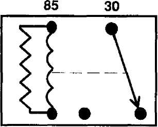
in step 2), check resistance between relay terminals No. 86 and 85.
See Fig. 2. Resistance should be 70-80 ohms. If resistance is not 70-
80 ohms, replace relay.
Disconnect negative battery terminal. Reconnect PCM
harness connector. Connect battery cable. Check fuel pump operation.
If fuel pump does not operate, see G - 2.5L & 4.0L TESTS W/CODES
article in the ENGINE PERFORMANCE Section and check PCM.
Not
Used (87A)
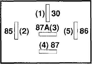
BOTTOM VIEW OF RELAY
86 87 87A
91D13972 DE-ENERGIZED RELAY
Fig. 2: Identifying Fuel Pump Relay Terminals Courtesy of Chrysler Corp.
IGNITION CHECKS
SECONDARY SPARK
Spark Test
Remove coil wire from distributor cap. Hold end of cable
about 1/4" from ground. Crank engine. Spark should be present and
constant. If spark is not present and constant, check coil and coil
wire resistance. Perform IGNITION PRIMARY test under IGNITION CHECKS.
If coil wire spark is present, ensure spark reaches spark
plugs. Check condition of rotor, cap, spark plug wires and spark
plugs. Repair or replace if necessary.
Spark Plug & Coil Wire Resistance Resistance should be 250-1000 ohms per inch.
Ignition Coil Resistance Test
Remove primary and secondary leads from ignition coil.
Using ohmmeter, check primary resistance between positive and negative
terminals of coil. See IGNITION COIL RESISTANCE table.
Check secondary resistance between center tower and
negative terminal of coil. See IGNITION COIL RESISTANCE table. Replace coil if readings are not within specification.
IGNITION COIL RESISTANCE TABLE- Ohms @ 75F (24C)
Application Ohms
Primary Diamond 97-1.18
Toyodenso 95-1.20
Secondary
Diamond 11,300-15,300
Toyodenso 11,300-13,300
IGNITION PRIMARY
NOTE: Perform SECONDARY SPARK under IGNITION CHECKS before proceeding with test.
Ensure battery has a minimum of 12.5 volts (9.5 cranking
volts) available to operate cranking system. Ensure battery cable
connections are clean and tight.
Using an analog voltmeter, backprobe the following wires
at the distributor. Touch positive lead to Tan/Yellow wire (Gray/Black
wire Grand Cherokee). Touch negative lead to Black/Light Blue wire.
Set voltmeter to 15-volt DC scale. Crank engine. If
voltmeter needle does not fluctuate between 0-5 volts, check related
circuits. If necessary, replace camshaft position sensor. If camshaft
position sensor is okay, but engine does not start, see G - 2.5L & 4.
0L TESTS W/CODES article in the ENGINE PERFORMANCE Section and check
PCM.
SUMMARY
If no faults were found while performing BASIC DIAGNOSTIC PROCEDURES, proceed to G - 2.5L & 4.0L TESTS W/CODES article in the ENGINE PERFORMANCE Section. If no hard codes are found in G - 2.5L & 4.0L TESTS W CODES, proceed to H - TESTS W/O CODES article in the ENGINE PERFORMANCE Section for diagnosis by symptom (i.e., ROUGH IDLE, NO START, etc.) or intermittent diagnostic procedures.