Ā
1993 Jeep Cherokee
1993 ENGINE COOLING
Chrysler Corp. Engine Cooling Fans
Jeep; Cherokee, Grand Cherokee, Wrangler
NOTE: Information for Grand Cherokee with 5.2L V8 engine is not available from manufacturer.
ELECTRIC COOLING FAN
On Cherokee 4.0L engine with heavy-duty cooling and/or air conditioning, an auxiliary electric fan operates whenever engine temperature exceeds 190F (88C), or air conditioner is on. If Powertrain Control Module (PCM) detects a fan control circuitry problem, a fault code will set.
NOTE: For more information on vehicle self-diagnostics, see
appropriate SELF-DIAGNOSTICS article in ENGINE PERFORMANCE.
TROUBLE SHOOTING & TESTING
Electric Cooling Fan Circuit
1) Ensure fuses No. 4 and 6 on Power Distribution Center
(PDC), near battery, are good. Ensure fan operates. See MOTOR under
COMPONENT TESTING. Remove cooling fan relay from PDC. Start engine. Using a test light, check for power at terminal No. 2 (Light Green/Red wire) of PDC. If test light does not illuminate, repair open circuit in Light Green/Red wire between terminal No. 2 and fuse No. 4.
Connect a jumper wire between terminal No. 2 (Light
Green/Red wire) and terminal No. 4 (Light Green wire) on PDC. If fan
does not operate, leave jumper wire connected. Unplug fan connector on
left side of fan shroud.
Using a test light, check for power at Light Green wire on
fan harness connector. If no power exists, repair Light Green wire
between fan harness connector and terminal No. 4 on PDC. If power
exists at Light Green wire, repair open circuit in Black wire between
fan harness connector and ground.
Turn ignition off. Reconnect fan motor connector. Remove
jumper wires. Reinstall relay. Connect Diagnostic Readout Box II (DRB-
II) to engine diagnostic connector. Connector is located in engine
compartment, next to PCM.
Start engine. Energize fan relay circuit by warming engine
until coolant temperature is higher than 190F (88C), or by turning
air conditioning on (if equipped). If relay clicks but fan does not
operate, check for poor relay connections at socket. If connections
are okay, test relay. See RELAY under COMPONENT TESTING.
If relay does not click, put DRB-II into voltmeter mode.
Measure voltage at cavity A1 (Dark Blue/White wire) in relay
connector. If voltage is less than 10 volts, repair open circuit in
Dark Blue/White wire between cavity A1 and fuse No. 6. If voltage is
10 volts or more, turn ignition off and reconnect relay.
Unplug connector from PCM. Examine connector. If connector
is okay, turn ignition on. With DRB-II in voltmeter mode, measure
voltage at terminal No. 31 (Dark Blue/Pink wire) on PCM harness
connector. If voltage is 10 volts or more, replace PCM. If voltage is
less than 10 volts, repair open circuit in Dark Blue/Pink wire between
PCM terminal No. 31 and PDC terminal No. 5.
COMPONENT TESTING
Motor
Unplug fan motor connector at left side of fan shroud. Connect a jumper wire from terminal "B" (Black wire) of fan motor connector to a known good engine ground. Using another jumper with a 25-amp in-line fuse, supply battery power to terminal "A" (Red wire) of fan motor connector. Service fan motor if it does not run.
Relay
Remove relay from Power Distribution Center (PDC). Connect
a self-powered test light between relay terminals No. 2 and 4. See
Fig. 1. Test light should indicate no continuity. Leave test light
connected.
Using a jumper wire, connect relay terminal No. 5 to a
good ground. Using another jumper with a 15-amp in-line fuse, supply
battery power to relay terminal No. 1. If test light does not indicate
continuity, replace relay.

Cherokee & Wrangler (2.5L Engine) Grand Cherokee (Without A/C)
Grand Cherokee (With A/C)
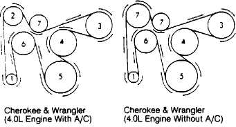
Alternator
A/C Compressor
Power Steering Pump
Water Pump
Crankshaft
Cooling Fan
Idler Pulley
93A75911
Fig. 1: Identifying Fan Relay Connector Terminals Courtesy of Chrysler Corp.
WIRING DIAGRAM
Also see appropriate chassis wiring diagram in WIRING
DIAGRAMS.

Fig.
93A28944
2: Electric Cooling Fan Wiring Diagram